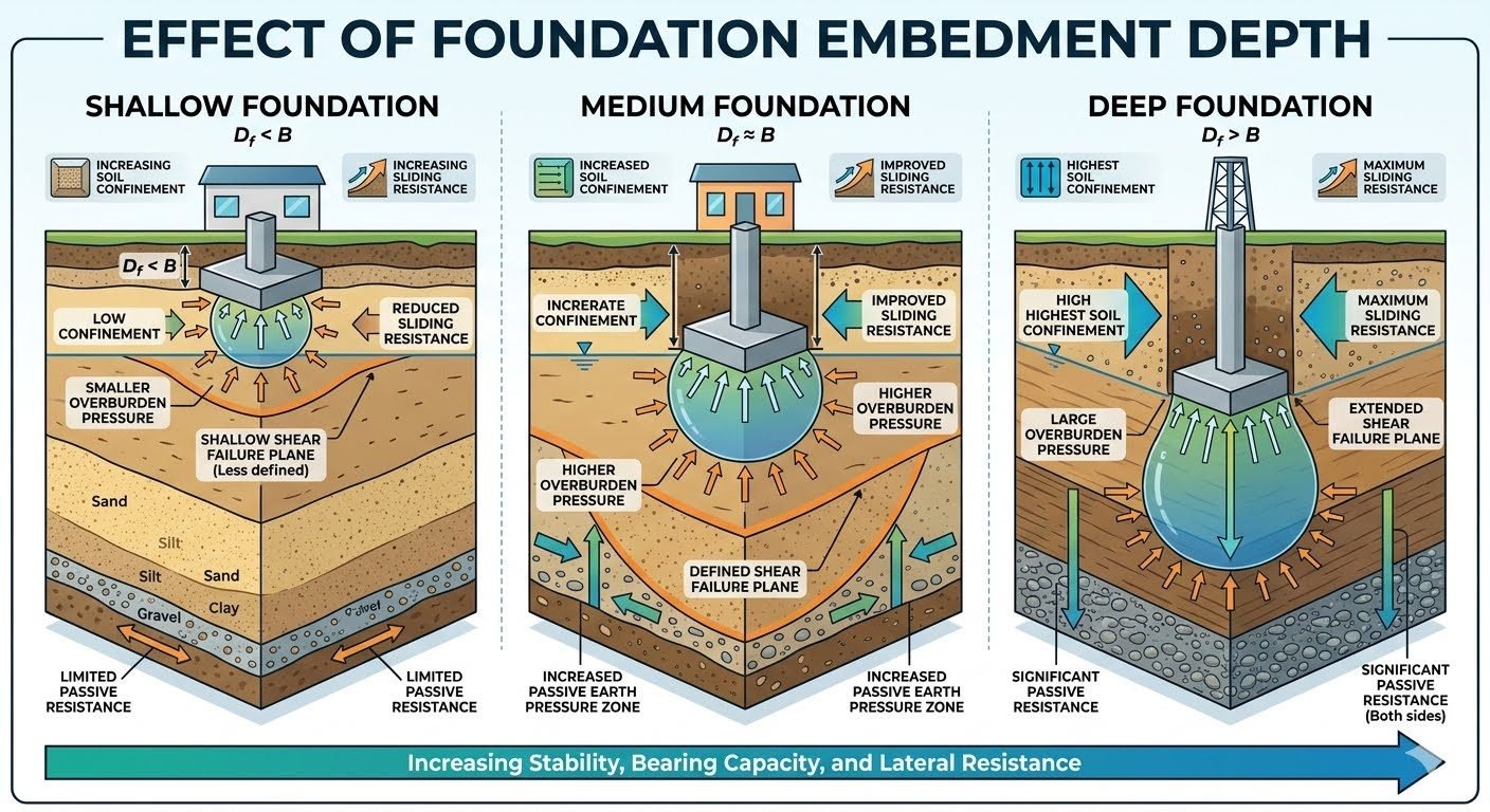
Foundation Embedment Depth Ratio Mechanics for Wind Loading
In my two decades of reviewing complex industrial structural designs, I have frequently observed that civil engineering teams hyper-focus on column diameters while underestimating the profound impact of foundation embedment depth. When extreme lateral wind loads strike massive vertical process columns or pipe racks, the stability of the entire structural system relies heavily on the embedment depth ratio, denoted as Df/B. This dimensionless ratio compares the foundation embedment depth (Df) directly against its base width (B), dictating whether the supporting soil acts as a shallow restraint or a deeply confined anchor.
Understanding how this ratio dictates soil mechanics allows us to optimize concrete volumes, prevent catastrophic sliding failures, and satisfy rigid deflection limits enforced by codes such as ASCE 7. Throughout this comprehensive design guide, I will deconstruct the distinct mechanical regimes of shallow, medium, and deep foundation embedment, providing actionable engineering calculations and industry-standard verification workflows.
Key Engineering Takeaways
- Df/B < 1 (Shallow Foundations): Dominated by base friction and negligible passive resistance, highly vulnerable to wind-induced overturning moments.
- Df/B ≈ 1 (Medium Foundations): Balanced mobilization of skin friction and localized passive earth pressure zones, offering moderate lateral stiffness.
- Df/B > 1 (Deep Foundations): Maximum soil confinement, deep shear failure planes, and substantial passive resistance acting along both foundation faces.
- Design Integration: Wind load eccentricity directly couples with embedment depth, requiring rigorous verification against geotechnical capacity limits.
Mechanics of Foundation Embedment Depth and Lateral Wind Stability
When designing industrial foundations exposed to severe atmospheric wind profiles, the primary structural concern is resisting overturning moments and lateral shear forces. The lateral resistance of a foundation is not merely a function of its self-weight multiplied by the concrete-soil interface friction coefficient. Instead, it is a complex tripartite interaction involving base sliding resistance, passive earth pressure mobilized along the embedded vertical faces, and deep-seated shear mobilization within the surrounding soil mass.
Per ASCE 7 design philosophy, wind velocity pressures translate into lateral shear forces applied at the center of pressure of above-ground structures. This induces an overturning moment (M) and a base shear (V). To counteract this, the embedment depth ratio (D_f/B) dictates the active mobilization of soil resistance. Let us examine the mathematical formulations and stress parameters governing these three distinct embedment regimes.
Shallow Foundation Regime (D_f/B < 1)
For shallow footings, such as isolated spread footings or mat foundations where the embedment depth is less than the foundation width, the passive earth pressure contribution is minimal. The total lateral resistance (R_lat) is primarily expressed as:
Where δ represents the friction angle between the concrete base and the subgrade soil, and P_p is the passive resistance. Because D_f is small, the height over which passive pressure acts is limited, resulting in a shallow, curved Prandtl or Rankine shear failure plane that breaks out quickly to the ground surface. Consequently, sliding safety factors often fall below required thresholds unless shear keys are introduced.
Medium Foundation Regime (D_f/B ≈ 1)
When the embedment depth approximately equals the foundation width, the geotechnical behavior transitions into a more robust confinement state. Overburden pressure (σ_v = γ · D_f) increases significantly, which directly enhances both the frictional resistance at the base and the shear strength parameters of the surrounding soil matrix.
In this medium regime, the passive pressure zone expands downward and outward. Using Rankine or Coulomb active-passive earth pressure theories, the passive resistance per unit width can be integrated over the embedment depth D_f:
Where γ is the effective soil unit weight, K_p is the coefficient of passive earth pressure, and c is soil cohesion. This expanded passive zone significantly curtails lateral displacement under cyclic wind gusts.
Deep Foundation Regime (D_f/B > 1)
For deep foundation elements, including massive caissons, drilled shafts, or deeply embedded block foundations where D_f substantially exceeds B, lateral resistance reaches its maximum efficiency. High confining pressures prevent premature localized soil yielding. The shear failure plane extends deep into the competent strata, mobilizing significant soil mass.
Critical Design Warning: Moment-Rotation Coupling
In deep foundations subjected to lateral wind loads, rotation occurs about a pivot point located at some fraction of the embedment depth. Neglecting the shift in the center of rotation can lead to unconservative passive pressure distributions, resulting in excessive foundation tilt and piping connection fatigue. Always cross-check geotechnical stiffness parameters against ASTM D3966 lateral load test standards.
Furthermore, deep embedment introduces significant skin friction along the vertical sides of the foundation block, acting in conjunction with deep passive wedges. This dual-resistance mechanism ensures that wind-induced overturning moments are safely transferred into the earth without exceeding allowable bearing pressures at the toe.
Structural Advantages
- Superior Sliding Resistance: Deep embedment ratios (D_f/B > 1) drastically increase passive earth pressure, eliminating the need for auxiliary concrete shear keys.
- Overturning Moment Mitigation: Higher overburden pressures create a larger restoring moment arm, reducing eccentric toe pressures under severe wind loads.
- Thermal and Frost Protection: Deep foundations anchor the structure below the active frost line and seasonal moisture variation zone, preventing volumetric soil movement.
- Enhanced Rotational Stiffness: Greater lateral confinement limits lateral translation and angular rotation, protecting sensitive piping and equipment alignments.
- Reduced Sensitivity to Scour: Deeply embedded elements maintain structural integrity even if surface soils experience erosion or grade degradation.
Engineering Disadvantages
- Escalated Excavation Costs: Deep earthwork requires extensive shoring, sheet piling, and soil stabilization, significantly increasing capital project expenditures.
- Groundwater Management Challenges: Excavating below the water table necessitates continuous dewatering systems, risking neighboring settlement issues.
- Construction Schedule Delays: Deep pours, curing times, and complex shoring installation extend project critical paths compared to shallow spread footings.
- Complex Geotechnical Testing: Accurate determination of high-depth passive pressure coefficients (K_p) requires advanced pressuremeter or dilatometer testing.
- Backfill Compaction Risks: Improperly compacted annular backfill around deeply embedded shafts fails to mobilize expected passive earth pressure.
Tall Industrial Distillation Columns
Petroleum refinery fractionators and distillation towers possess extreme aspect ratios, subjecting their foundations to massive wind-induced overturning moments. Engineers specify deep embedment ratios (D_f/B > 1.5) utilizing massive octagonal concrete pedestals. This depth ensures that the resultant load vector remains well within the middle third of the base, preventing tension cracking in the subgrade and excessive tilting that would otherwise stress interconnecting process piping.
Pipe Racks in Hurricane-Prone Coastal Zones
Heavy industrial pipe racks carrying multi-tier utility lines present massive projected surface areas to hurricane-force winds. In coastal facilities with soft topsoils, shallow footings fail under lateral shear. Civil design teams deploy deeply embedded pile caps or caisson-supported tie beams. By utilizing the upper strata’s passive resistance and transferring loads to competent bearing layers, structural engineers guarantee compliance with ASCE 7 wind load combinations.
High-Voltage Electrical Transmission Towers
Lattice electrical transmission towers experience severe lateral wind shear combined with high uplift forces from conductor stringing. Foundation design relies on embedded stub angles and grillage footings where D_f/B ratios approach 2.0. The deep burial mobilizes cone-out soil weight, providing the necessary ballast against wind uplift while leveraging surrounding earth confinement to resist lateral overturning.
Exhaust Stacks and Flare Structures
Industrial flare stacks and flue gas chimneys are slender cantilever structures highly susceptible to cross-wind vortex shedding and gust buffeting. Their ring-wall foundations require careful embedment depth tuning. By embedding the massive annular ring foundation into dense granular soils, structural engineers establish a high-stiffness deformation modulus that restricts lateral deflection at the stack base within allowable operational tolerances.
Foundation Embedment Depth Comparison Metrics
In my geotechnical engineering practice, evaluating the precise ratio of embedment depth to foundation width (Df/B) is vital for predicting structural behavior under extreme environmental conditions. When designing industrial supports subjected to severe wind regimes, categorizing foundations into shallow, medium, and deep profiles dictates the governing failure mechanisms defined in ASCE standards. The structural integrity depends heavily on mobilization of passive earth pressure and shear resistance along the footing perimeter.
The following matrix summarizes the mechanical characteristics, failure plane geometries, and lateral resistance profiles across the three primary embedment categories. This engineering data serves as a baseline for calculating sliding safety factors in accordance with ASME codes governing structural stability.
| Embedment Category | Ratio Parameter (Df/B) | Confinement Level | Shear Failure Plane | Lateral Resistance Mechanism |
|---|---|---|---|---|
| Shallow Foundation | Df < B | Low Confinement | Shallow, less-defined Prandtl mechanism | Friction base sliding, minimal passive resistance |
| Medium Foundation | Df approx B | Moderate Overburden Pressure | Developing wedge with clear slip surfaces | Combined base friction and active/passive earth pressure |
| Deep Foundation | Df > B | Maximum Soil Confinement | Extended deep shear failure with skin friction | Dominant shaft resistance and full passive zones |
Note: Tabulated values assume homogeneous cohesionless or cohesive-frictional backfill compacted to 95 percent modified Proctor density per standard geotechnical specifications.
Technical Mapping & Specifications Matrix
Establishing a standardized nomenclature is essential for cross-functional engineering teams analyzing foundation embedment dynamics. In industrial piping and structural supports, calculating wind overturning moments requires precise mapping of soil-structure interaction parameters. Utilizing standardized entity designations ensures complete compliance with ASTM soil testing standards and international building codes.
The matrix below outlines the critical mechanical parameters, associated structural acronyms, governing formulas, and corresponding design codes utilized throughout rigorous foundation stability assessments. Each entity directly influences the computed safety factor against lateral sliding and rotational tipping.
| Engineering Entity | Acronym / Symbol | Physical Parameter | Governing Standard |
|---|---|---|---|
| Embedment Depth Ratio | Df/B | Burial depth relative to foundation width | ASCE 7-22 Wind Load Provisions |
| Passive Earth Pressure | Pp | Resistance force mobilized by soil compression | ASTM D3080 Direct Shear |
| Overburden Pressure | q0 | Vertical soil stress acting at foundation base | ASME STS-1 Standards |
| Sliding Safety Factor | FS_slide | Ratio of resisting forces to lateral wind loads | ASCE 37 Design Loads |
Reference implementation: All parameters must be integrated into finite element geotechnical models to verify non-linear soil yielding under dynamic wind gusts.
Foundation Embedment and Lateral Stability Verification Checklist
Foundation embedment depth verification requires rigorous field inspection before backfilling operations commence. In my piping layout reviews, overlooking soil compaction and embedment dimensions frequently leads to excessive lateral displacement under heavy wind loading. Field engineers must strictly follow structured validation protocols to guarantee compliance with ASME structural standards.
Execute the following systematic site checks during excavation, subgrade preparation, and backfill placement to ensure the foundation embedment ratio (Df/B) achieves designed resistance thresholds.
Mandatory Field Inspection Protocol
- [ ] Excavation Depth Verification: Confirm actual vertical excavation depth matches structural drawings to satisfy the target Df/B ratio before blinding concrete placement.
- [ ] Subgrade Soil Density: Perform nuclear gauge or sand cone density testing on the foundation subgrade, ensuring a minimum compaction level of 95 percent modified Proctor.
- [ ] Backfill Compaction Control: Inspect side-wall backfill placement around deep and medium foundations, verifying uniform layer lifts and moisture content per ASTM D698 specifications.
- [ ] Passive Zone Integrity: Ensure no uncompacted utility trenches or loose soil zones compromise the passive earth pressure wedge adjacent to the embedded foundation walls.
- [ ] Groundwater Control: Verify dewatering systems maintain water tables at least two feet below the foundation base during concrete curing and backfill operations.
- [ ] Shear Key Alignment: Check dimensions and reinforcement continuity of any integrated shear keys designed to enhance base sliding resistance under wind loads.
Compliance sign-off from both the lead geotechnical engineer and the structural discipline head is mandatory prior to releasing the excavation for structural erection.
Field Case Study: Real-World Application
A heavy industrial facility located in a high-wind coastal corridor experienced severe lateral displacement and rotational tilting of elevated pipe rack foundations during a major tropical storm. The original civil design utilized shallow pad footings where the embedment depth ratio was maintained below unity (Df/B < 0.5), neglecting adequate passive soil confinement.
Problem Analysis
Lateral wind forces acting on the elevated piping tiers generated overturning moments that exceeded the sliding resistance capacity of the shallow pad footings.
- Low soil confinement resulted in immediate mobilization failure of passive earth pressure zones.
- Shallow Prandtl shear failure planes developed rapidly under cyclic wind gusts, reducing base friction.
- Absence of sufficient overburden pressure caused uplifting on the windward foundation edges.
- Lateral sliding displacement exceeded allowable piping stress limits, threatening flange leakage.
Engineering Remediation & Outcome
Retrofitting the facility with deep piers and increasing the embedment depth ratio to Df/B greater than 2.0 successfully stabilized all pipe rack supports against extreme wind loads.
- Passive earth pressure resistance increased by over three hundred percent along the foundation shafts.
- Extended shear failure planes successfully mobilized deep, dense soil strata with higher shear strength parameters.
- Overburden pressure eliminated edge uplift and doubled the sliding safety factor.
- Post-remediation wind tunnel and displacement monitoring confirmed zero detrimental lateral movement during subsequent storm events.
Engineering Recommendation: For all industrial structures subject to significant lateral wind loading, design engineers must mandate an embedment depth ratio of Df/B greater than 1.0, ensuring full mobilization of passive soil resistance and adherence to ASCE design guidelines.
Frequently Asked Engineering Questions
How does the embedment depth to foundation width ratio (Df/B) affect sliding resistance?
- Shallow conditions (Df/B less than 1) rely heavily on base friction alone due to minimal passive soil confinement.
- Medium embedment (Df/B approximately 1) introduces significant sidewall resistance, balancing sliding and overturning moments.
- Deep embedment (Df/B greater than 1) engages deep passive wedge mechanisms, drastically reducing base shear demands.
What specific failure mechanisms govern shallow foundations under heavy lateral wind loading?
- Base sliding occurs when horizontal wind shear exceeds the combined friction and minimal passive resistance.
- Edge rocking develops when eccentric overturning moments reduce contact pressure on the windward side to zero.
- Soil heave can happen immediately adjacent to the foundation edge due to lack of heavy confining surcharge.
When should an engineer specify a medium embedment depth rather than a shallow spread footing?
- High-wind open terrain sites where tall vertical equipment experiences massive overturning moments.
- Locations with upper soil layers possessing low drained friction angles requiring burial into denser strata.
- Sites requiring frost protection depth that naturally satisfies minimum geotechnical embedment thresholds.
How do deep foundations handle the extended shear failure planes caused by lateral loads?
- Extended embedment forces the failure surface to develop deep underground where soil confinement is maximized.
- Bending moments are transferred safely along the shaft into competent load-bearing geological layers.
- Combined axial and lateral resistance is achieved through skin friction and comprehensive lateral subgrade reaction.
What design codes govern the calculation of passive earth pressure for embedded foundations?
- Rankine theory assumes frictionless vertical failure planes and is conservative for shallow depths.
- Coulomb theory accounts for wall friction but can overestimate passive resistance in dense soils if wall roughness is high.
- Three-dimensional wedge corrections must be applied when foundation width is constrained relative to embedment depth.
Field Recommendation
When designing large industrial foundations subjected to severe lateral wind loads, I advise applying rigorous geotechnical verification rather than relying on minimum geometric rules of thumb. My direct field recommendations for structural and geotechnical engineers include:
- Prioritize Embedment over Base Widening: If sliding shear checks fail on a shallow spread footing under wind loading, increase the embedment depth ratio (Df/B) toward 1.0 rather than excessively enlarging the pad width, as passive resistance provides superior efficiency.
- Enforce Compaction Quality Control: For all medium and deep embedded footings, mandate strict backfill compaction standards around the perimeter per ASTM D698 to ensure the calculated passive pressure zones actually develop in the field.
- Account for Seasonal Moisture Variations: In expansive or frost-susceptible soils, never take credit for upper-level passive resistance within the top 0.5 meters when evaluating extreme wind load combinations.
- Utilize Pier Elements for High Overturning Moments: When Df/B exceeds 2.0 due to extreme tower structures, transition from massive block foundations to drilled shafts or battered pile caps to control deep shear failure planes effectively.
Complete Course on
Piping Engineering
Check Now
Key Features
- 125+ Hours Content
- 500+ Recorded Lectures
- 20+ Years Exp.
- Lifetime Access
Coverage
- Codes & Standards
- Layouts & Design
- Material Eng.
- Stress Analysis
