Foundation Design Safety Factors: Mastering Gamma Multipliers and Load Combinations
In my two decades of executing structural and piping engineering designs across heavy industrial complexes, I have repeatedly observed that the integrity of an entire structural asset depends directly on the proper application of geotechnical and structural safety factors. When evaluating foundation design safety factors, engineers must bridge the gap between idealized numerical models and the unpredictable variability of in-situ soil mechanics.
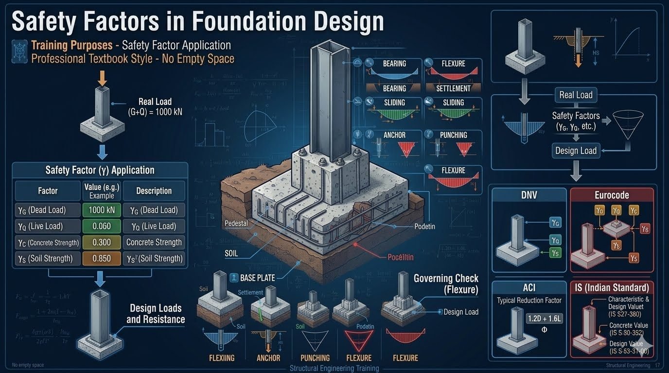
Applying these safety factors to a real load of dead plus live load produces the rigorous design load used for checking flexure, bearing, settlement, sliding, anchor bolts, and punching shear failure modes. Different regulatory frameworks approach this conversion through distinct mechanisms, requiring a precise understanding of partial safety factor theory.
Key Engineering Takeaways
- Partial safety factors isolate uncertainties in permanent actions, variable loads, material resistance, and geotechnical properties.
- Ultimate limit state checks require simultaneous verification against bearing capacity, sliding stability, and overturning.
- Flexural reinforcement design within concrete footings typically governs the primary sizing and reinforcement layout.
Gamma Multipliers in Foundation Design and Limit State Formulations
Foundation design safety factors function by separating the uncertainties of load introduction from the capacities of structural concrete and subgrade soil mechanics. In modern limit state design, unadjusted service loads are multiplied by specific partial safety factors known as gamma factors to yield factored design loads.
For permanent actions such as structural self-weight, equipment dead weight, and permanent soil overburden, the partial safety factor gamma-G is applied. For transient variable actions like operational live loads, wind forces, and seismic accelerations, the partial safety factor gamma-Q accounts for statistical load variations.
Deconstructing Partial Safety Factor Formulations
When analyzing a reinforced concrete pad or pile cap, the structural design value of an action (Ed) is calculated as a function of the characteristic actions multiplied by their respective gamma multipliers. For instance, consider a combined load condition where dead load is 1000text{ kN} and live load is 300text{ kN}. Under Eurocode conventions, utilizing γ_G = 1.35 and γ_Q = 1.50 yields a factored design load of (1000 × 1.35) + (300 × 1.50) = 1800text{ kN}.
Conversely, American codes such as ACI 318 utilize combined load factors like 1.2D + 1.6L, bypassing individual material factor splitting in favor of calibrated ultimate strength combinations. Regardless of the regional code philosophy, the underlying physical foundation must satisfy the exact resistance threshold dictated by the governing failure mode.
Critical Geotechnical Warning
Never apply structural load factors blindly to geotechnical bearing capacity equations without accounting for soil strength reduction factors (γ_M or γ_R). Neglecting soil parameter degradation under cyclic industrial vibration can lead to catastrophic differential settlement even when structural concrete checks pass comfortably.
Evaluating Critical Failure Modes in Foundation Engineering
The primary objective of applying gamma multipliers is to prevent distinct structural and geotechnical failure modes. The most critical failure mechanism is flexural yielding of the bottom reinforcement mat, which typically governs the overall thickness and steel area of large equipment foundations.
Punching shear is another critical check, especially around heavy centrifugal compressor pedestals or heavily loaded column bases. If the concrete shear capacity factored by γ_C is exceeded, sudden brittle shear failure occurs without adequate warning. Sliding and overturning checks must also be verified using favorable and unfavorable gamma-G multipliers to bound the stability envelope accurately.
| Parameter / Factor | Eurocode Symbol | Typical Range / Value | Governing Standard |
|---|---|---|---|
| Permanent Load Factor | γ_G | 1.00 to 1.35 | EN 1990 / EN 1997 |
| Variable Load Factor | γ_Q | 0.00 to 1.50 | EN 1990 |
| Concrete Strength Factor | γ_C | 1.25 to 1.50 | EN 1992-1-1 |
| Soil Strength Parameter | γ_M / γ_φ | 1.00 to 1.25 | EN 1997-1 |
Understanding these interactions ensures that piping stress engineers and civil designers maintain safe nozzle load allocations on connected equipment. When thermal piping forces react against anchor bolts embedded in concrete blocks, the combined load vector directly influences the foundation safety margin.
Advantages of Partial Safety Factors
- Explicit Uncertainty Isolation: Separates loading uncertainty from material strength variability for precise risk assessment.
- Global Code Harmonization: Aligns geotechnical and structural calculations under a unified limit state framework.
- Optimized Material Usage: Prevents over-design by tailoring safety multipliers to specific action types and load durations.
- Clear Failure Attribution: Identifies whether structural yielding or soil bearing failure governs the design boundary.
- Adaptability to Testing: Accommodates statistical site-specific soil data adjustments easily within γ_M parameters.
Disadvantages and Limitations
- Increased Calculation Complexity: Requires managing multiple load combination iterations and unfavorable/favorable multiplier states.
- Divergent Regional Standards: Conflicts between Eurocode partial factors and ACI load combinations complicate international projects.
- Potential Conservatism Trap: Multiplying worst-case actions by worst-case soil degradation can yield unachievable foundation footprints.
- High Dependency on Quality Data: Inaccurate initial site investigation reports render partial safety factor calculations unreliable.
- Training Overhead: Demands rigorous engineering judgment to select appropriate design approaches (e.g., Approach 1 vs. Approach 2 in EN 1997).
Centrifugal Compressor Skid Foundations
High-speed rotating equipment transmits severe dynamic vibratory forces into concrete block foundations. Engineers apply specialized gamma multipliers to combine static equipment weight with dynamic unbalance loads, ensuring the combined design load prevents both resonance and subgrade soil liquefaction.
Petrochemical Pipe Rack Column Bases
Heavy industrial pipe racks carry hundreds of high-temperature process lines generating massive thermal anchor movements. Foundation design safety factors must account for simultaneous eccentric bending moments, friction forces, and variable live loads from maintenance laydowns without exceeding allowable bearing pressures.
Storage Tank Ringwall and Mat Foundations
Large-diameter atmospheric crude oil storage tanks induce immense ringwall hydrostatic pressures and uniform soil subgrade reactions. Partial safety factors for liquid fill loads (γ_Q) and steel shell dead loads (γ_G) dictate the exact settlement tolerances and edge shear reinforcement sizing.
Offshore Platform Jacket Pile Connections
Marine engineering structures withstand relentless wave action, wind overturning moments, and current drag forces governed by DNV standards. Applying strict gamma-G and gamma-Q multipliers ensures pile penetration depth and grouted sleeve shear capacities withstand extreme 100-year storm events.
High-Voltage Electrical Substation Transformer Pads
Massive oil-filled electrical transformers require robust concrete containment sumps and heavily reinforced dead-man anchorages. Safety factor formulations must incorporate seismic inertia multipliers alongside operational short-circuit mechanical forces to guarantee zero structural displacement during fault conditions.
Foundation Safety Factor Parameters and Code Comparison Matrix
Foundation design safety factors vary significantly across international structural and geotechnical codes. Understanding these numerical differences is critical for piping and structural engineers when evaluating piping support structures, heavy equipment skids, and massive foundation mats. The following table provides a comprehensive comparison of partial safety factors and load combination conventions across major engineering standards, including ISO 2394, Eurocode 7, ACI 318, and IS codes.
Each standard establishes specific multipliers for permanent actions, variable actions, material properties, and soil resistance to ensure adequate structural reliability under ultimate limit state conditions.
| Design Code / Standard | Dead Load Factor (gamma-G) | Live Load Factor (gamma-Q) | Material Factor (gamma-C/S) | Primary Failure Mode Governed |
|---|---|---|---|---|
| Eurocode 7 (EN 1997) | 1.35 (Unfavorable Permanent) | 1.50 (Variable Actions) | 1.25 (Concrete) / 1.25 (Soil Shear) | Geotechnical Bearing & Flexure |
| ACI 318 (LRFD Approach) | 1.20 (Combined Dead Load) | 1.60 (Combined Live Load) | 0.75 to 0.90 (Strength Reduction phi) | Punching Shear & One-Way Flexure |
| IS 456 / IS 1904 (Indian) | 1.50 (Characteristic Dead Load) | 1.50 (Characteristic Live Load) | 1.50 (Concrete) / 1.15 (Steel Reinforcement) | Overturning, Sliding, & Bending Moment |
| DNV-OS-C101 (Offshore) | 1.30 (Permanent Structure) | 1.30 to 1.50 (Environmental/Live) | 1.15 (Material Resistance) | Sliding, Uplift, & Cyclic Fatigue |
Note: Multipliers shown reflect standard ultimate limit state (ULS) conditions. Special load combinations involving seismic or impact events require specific code-defined reduction factors.
Technical Mapping & Specifications Matrix
To maintain absolute rigor in foundation structural design, engineers must map physical parameters and structural entities directly to recognized international codes. The following entity specification matrix outlines the key nomenclature, variable definitions, and governing criteria utilized across geotechnical and structural engineering software packages.
This mapping ensures that software inputs for dead load multipliers, live load fractions, and soil friction angles correspond correctly to regulatory expectations.
| Entity Terminology | Symbol / Notation | Engineering Definition | Governing Standard |
|---|---|---|---|
| Permanent Action Multiplier | gamma-G | Partial safety factor applied to self-weight and permanent dead loads. | EN 1990 / EN 1997 |
| Variable Action Multiplier | gamma-Q | Partial safety factor applied to operational live loads and environmental forces. | EN 1990 |
| Concrete Material Factor | gamma-C | Resistance factor reducing characteristic compressive strength of concrete. | EN 1992-1-1 |
| Soil Shear Strength Factor | gamma-M / gamma-S | Factor applied to soil cohesion and internal friction angle in bearing checks. | EN 1997-1 |
| Strength Reduction Factor | phi | Multiplier applied to nominal resistance in LRFD design methodologies. | ACI 318 Chapter 9 |
Entity validation is mandatory prior to generating finite element mesh models for large industrial equipment foundations.
Site Verification Checklist for Foundation Design Safety Factors
Foundation safety factor verification requires a methodical workflow combining geotechnical site data, structural loading summaries, and rigorous code compliance checks. In my engineering practice, skipping any verification step during the pre-construction review phase frequently leads to differential settlement or premature structural distress under heavy cyclic piping loads.
Execute the following systematic verification protocol before finalizing construction drawings or submitting calculation packages for third-party approval.
Engineering Site Verification & Safety Factor Protocol
-
2. Apply Code-Specific Multipliers: Ensure partial safety factors (gamma-G, gamma-Q) are correctly assigned to permanent and variable actions without mixing contradictory regional standards.
-
3. Check Geotechnical Bearing Capacities: Validate that ultimate bearing resistance incorporates appropriate soil material safety factors (gamma-S) and matches insitu borehole shear test data.
-
4. Evaluate Flexural and Shear Demands: Confirm that ultimate design bending moments and punching shear forces from factored loads (1.2D + 1.6L or Eurocode equivalent) do not exceed nominal concrete section capacities.
-
5. Perform Overturning and Sliding Checks: Verify that stabilizing moments derived from dead weight exceed overturning overturning moments by a minimum factor of safety of 1.5 under worst-case wind and seismic combinations.
Document all calculation deviations and retain signed geotechnical investigation logs alongside structural design sheets for complete project traceability.
Field Case Study: Real-World Application
On a major refinery expansion project in the Gulf Coast, our engineering team evaluated a massive reciprocating compressor foundation experiencing severe micro-vibrations and localized soil settlement. The initial design had utilized generic load combinations without adequately separating permanent dead load multipliers from dynamic machinery operational forces.
Engineering Problem Identified
Differential settlement and flexural cracking occurred because the foundation design neglected proper gamma-Q live load amplification for unbalanced dynamic inertia forces.
- Underestimated dynamic load amplification factors from high-speed reciprocating compressor strokes.
- Inadequate soil strength reduction (gamma-S) applied to saturated clay layers beneath the mat perimeter.
- Flexural reinforcement sizing based solely on static dead weights rather than combined cyclic loading regimes.
- Overturning safety margin falling below the mandatory 1.5 threshold during simultaneous wind and surge events.
Engineering Outcome & Remediation
Applying rigorous Eurocode and ACI safety factor conventions corrected load paths and eliminated structural distress.
- Recalculated all design loads using explicit gamma-G (1.35) and gamma-Q (1.50) partial safety factors.
- Injected low-viscosity polyurethane grout to densify sub-grade soils and restore uniform bearing capacity.
- Added supplementary top rebar matting to increase one-way and two-way flexural crack resistance.
- Established permanent settlement monitoring markers to track long-term foundation stability under operating conditions.
Final Recommendation: Always enforce strict partial safety factor multipliers during initial foundation sizing, ensuring dynamic machinery skids account for combined dead and live load extremes per ASCE 7 and EN 1997 standards.
Frequently Asked Engineering Questions
How do partial safety factors for loads differ from material resistance factors in Eurocode 7?
- Load factors (gamma-G, gamma-Q) amplify permanent and variable actions.
- Material factors (gamma-C, gamma-S) divide characteristic shear and compressive strength.
- This dual approach prevents hidden safety duplication in complex geotechnical systems.
Why do ACI 318 load combinations use combined factors instead of separate individual multipliers?
- Standardized multipliers reflect historical reliability analyses for reinforced concrete elements.
- Combined factors reduce manual calculation errors during fast-paced structural design checks.
- Specialized combinations incorporate wind, seismic, and fluid pressures as required by ASCE 7.
What is the primary failure mode checked during foundation design safety evaluations?
- One-way and two-way punching shear dictate minimum concrete slab depth.
- Flexural reinforcement prevents tensile cracking under eccentric moment loads.
- Geotechnical settlement limits protect superstructure frames from excessive differential movement.
How do Indian Standard codes handle characteristic values versus design values?
- Characteristic material strength is divided by material safety constants like 1.15 for steel.
- Applied service loads are multiplied by specific load factors corresponding to load origin.
- Ultimate limit state equations combine these factored values for safe foundation proportioning.
Why must geotechnical and structural safety factors be coordinated on industrial projects?
- Geotechnical reports must supply characteristic soil parameters compatible with selected design codes.
- Structural software models need accurate boundary spring stiffness derived from factored soil reactions.
- Anchor bolt and pedestal interfaces must transfer ultimate loads without premature local crushing.
Field Recommendation
Based on my two decades of reviewing heavy industrial foundations, I advise engineering teams to establish code alignment early in the project lifecycle to prevent costly redesigns during detailed drafting. Here are my specific recommendations for managing safety multipliers and foundation design:
- If working on international multi-jurisdictional projects, choose Eurocode 7 design approaches only when geotechnical site data provides robust statistical soil testing, as partial material factors require high confidence intervals to avoid oversized footprints.
- When designing heavily loaded equipment skids on variable soils, select ACI 318 combined load factors alongside rigorous finite element soil spring modeling to accurately capture localized punching shear stresses near anchor bolt clusters.
- Never mix partial factor conventions from different standards within the same calculation sheet; ensure that gamma-G and gamma-Q load multipliers strictly correspond to the matching gamma-C and gamma-S resistance standards.
- Prioritize explicit sliding and overturning checks whenever lateral wind or seismic forces exceed thirty percent of total dead load, as sliding stability frequently governs slender foundation geometries before bearing pressure becomes critical.
Complete Course on
Piping Engineering
Check Now
Key Features
- 125+ Hours Content
- 500+ Recorded Lectures
- 20+ Years Exp.
- Lifetime Access
Coverage
- Codes & Standards
- Layouts & Design
- Material Eng.
- Stress Analysis
