What is a Foot Valve? Working, Types, and Foot Valve vs Check Valve
You have just finished installing a high-capacity centrifugal pump, but every time you shut it down, the suction line empties, and the system loses its prime. Restarting requires manual intervention, wasting hours of operational time and risking mechanical seal failure. This common engineering headache is almost always solved by one critical component: the Foot Valve. Far more than just a submerged check valve, it is the gatekeeper of your pump’s NPSH and operational readiness.
In this comprehensive guide, we analyze the mechanical architecture of the foot valve, evaluate material selection for corrosive environments, and provide a definitive technical comparison between a standard check valve and its specialized suction-side counterpart.
Key Takeaways
- Priming Security: The primary role of a foot valve is to maintain a constant column of liquid in the suction pipe to prevent pump dry-runs.
- Integrated Filtration: Unlike standard valves, these include high-area strainers to protect the pump impeller from debris.
- Pressure Management: Proper selection minimizes “cracking pressure” to ensure the pump operates within its suction lift limits.
What is a Foot Valve?
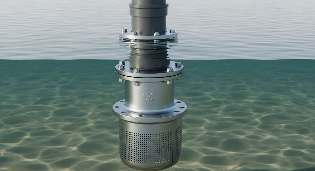
A Foot Valve is a specialized non-return valve installed at the bottom of a pump suction pipe. It functions by allowing fluid to flow toward the pump while preventing backflow into the source. This keeps the suction line primed, protects the pump from dry starts, and filters debris via an integrated strainer.
“In my 20 years of field engineering, I have seen more pumps destroyed by ‘cheap’ foot valves than by almost any other suction-side failure. If your foot valve has a high pressure drop, you are essentially strangling your pump’s performance before the fluid even reaches the impeller.”
— Atul Singla, Founder of Epcland
Table of Contents
Complete Course on
Piping Engineering
Check Now
Key Features
- 125+ Hours Content
- 500+ Recorded Lectures
- 20+ Years Exp.
- Lifetime Access
Coverage
- Codes & Standards
- Layouts & Design
- Material Eng.
- Stress Analysis
Foot Valve Engineering Challenge
Test your knowledge on suction-side hydraulics.
1. What is the primary hydraulic purpose of installing a Foot Valve?
The Engineering Principle: How a Foot Valve Works
The mechanical operation of a Foot Valve is governed by differential pressure. When the centrifugal pump is activated, it creates a partial vacuum in the suction line. This atmospheric pressure imbalance forces the valve’s internal disc or poppet to lift off its seat, allowing fluid to enter the system. Because the valve is installed at the lowest point of the suction lift, it remains fully submerged, ensuring that air cannot enter the column.
Once the pump stops, the weight of the fluid column above the valve, combined with gravity and often an internal spring mechanism, instantly forces the valve back into its seated position. This “check” action traps the liquid within the suction pipe. In technical terms, this maintains the static head required for the pump to restart without the need for manual priming. According to hydraulic standards outlined by the American Society of Mechanical Engineers (ASME), maintaining this prime is critical for preventing cavitation and mechanical seal dry-running.
Critical Requirements for Foot Valve Installation
Installing a Foot Valve requires precise adherence to suction-side geometry. For the valve to function effectively, it must be positioned far enough from the bottom of the reservoir to avoid sucking up silt, yet deep enough to prevent the formation of surface vortices. A common engineering rule of thumb is to submerge the valve at a depth of at least four to five times the pipe diameter.
Furthermore, the total pressure drop across the valve and strainer must be calculated during the system design phase. If the Foot Valve creates excessive resistance, the Net Positive Suction Head Available (NPSHa) may drop below the pump’s required NPSHr, leading to catastrophic impeller erosion.
Functions of the Strainer in a Foot Valve Assembly
The integrated strainer is what differentiates a Foot Valve from a standard non-return valve. Its primary functions include:
- Impeller Protection: It blocks large debris, stones, and organic matter that could clog the pump’s internal passages or break the impeller vanes.
- Flow Streamlining: A well-designed strainer helps in smoothing the flow profile of the entering fluid, reducing turbulence at the valve seat.
- Extended Maintenance Cycles: By filtering at the source, it prevents the buildup of sediment in the upper piping sections.
Key Performance Features of a Foot Valve
Modern industrial Foot Valves are engineered with specific features to handle harsh environments. These include a high “open-area-to-pipe-area” ratio in the strainer—often 3:1 or 4:1—to minimize head loss. Additionally, many designs utilize a “silent-close” feature where a spring-assisted poppet closes slightly before the flow reverses, effectively eliminating the hydraulic shock known as water hammer.
Another critical feature is the self-cleaning capability found in advanced models, where the exterior geometry of the strainer is designed to shed debris naturally through ambient fluid movement.
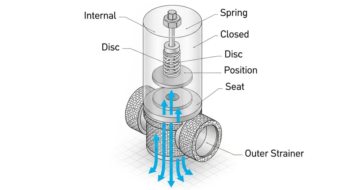
Internal Components of Industrial Foot Valves
The reliability of a Foot Valve depends on its internal architecture. While designs vary between manufacturers, high-performance valves adhere to strict tolerances defined by American Petroleum Institute (API) standards for sealing integrity. The core components include the valve body (the housing), the disc or poppet (the moving element), the seat (the sealing surface), and the spring.
In heavy-duty applications, the valve seat is often reinforced with O-rings or resilient elastomers to ensure a bubble-tight seal even at low backpressure. The strainer basket is typically threaded or bolted to the body, allowing for easy removal and cleaning during scheduled shutdowns.
Material Selection for Foot Valves (Corrosion & Wear)
Selecting the correct metallurgy is the most critical decision for a piping engineer. Because the Foot Valve is permanently submerged, it is highly susceptible to galvanic corrosion and pitting. Standard cast iron is suitable for clean water, but for seawater or chemical applications, Duplex Stainless Steel or Bronze is mandatory to prevent premature failure.
| Material Type | Typical Application | Corrosion Resistance |
|---|---|---|
| Cast Iron / Ductile Iron | Agriculture & Irrigation | Low |
| Stainless Steel (316) | Chemical & Food Processing | High |
| PVC / Polypropylene | Water Treatment / Corrosive Fluids | Very High (Non-Metallic) |
| Bronze / Gunmetal | Marine & Seawater Suction | Excellent (Saltwater) |
Common Types of Foot Valves
The choice of Foot Valve geometry is dictated by the viscosity of the fluid and the required flow rate. Spring-Loaded Poppet Valves are the industry standard for general water use, offering fast closure. Ball Foot Valves utilize a weighted ball that floats or sinks into position, making them ideal for viscous fluids or slurries where a standard hinge might clog.
For large-diameter pipes in municipal waterworks, Flapper Type Foot Valves are preferred. These utilize a hinged disc similar to a swing check valve, which provides a large flow area and very low pressure drop, though they are more prone to water hammer if not properly dampened.
Comparative Analysis: Foot Valve vs Check Valve
While both are non-return valves, the Foot Valve vs Check Valve debate is settled by installation location and feature set. A check valve is an inline component designed to handle high pressures and prevent backflow in discharge lines. In contrast, a Foot Valve is designed specifically for the suction end, featuring an integrated strainer and optimized for operation at low cracking pressures.
Using a standard check valve at the bottom of a suction line without a strainer would lead to immediate pump damage. Furthermore, standard check valves often have higher spring tension than a dedicated Foot Valve, which could starve the pump of fluid in high-lift scenarios.
EPCLand YouTube Channel
2,500+ Videos • Daily Updates
Foot Valve Head Loss & NPSH Impact Calculator
Estimate the pressure drop (Head Loss) across your foot valve to ensure your pump maintains sufficient NPSHa. High head loss at the suction end is the leading cause of cavitation.
Case Study: Solving Cavitation in Municipal Water Suction
Operational Breakdown: The Priming Paradox
In early 2024, a municipal water station in Haryana reported frequent pump tripping and high-frequency vibration during start-up cycles. Despite having a functional Foot Valve, the system required manual priming every 48 hours. Upon technical audit, it was discovered that the existing cast-iron foot valve had suffered from “micro-seepage” due to sediment buildup on the rubber seat.
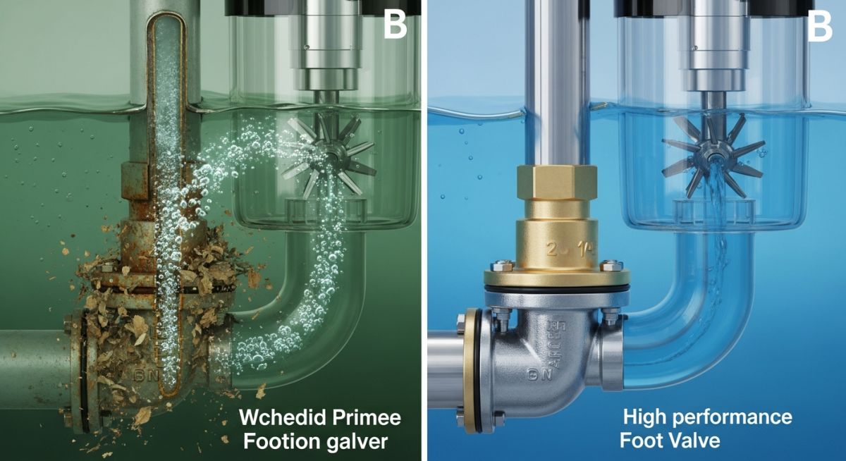
The Problem
- Leakage: Fluid drained back to the source overnight.
- NPSH Loss: High resistance from a partially clogged strainer.
- Material: Heavy corrosion on the poppet guide caused sticking.
The Engineering Solution
- Replacement: Installed a 316 Stainless Steel Foot Valve.
- Design Change: Switched from a poppet to a “Silent-Check” spring-loaded disc.
- Filtration: Integrated a high-flow basket strainer with 4x pipe area.
Outcome: Manual priming was eliminated entirely. The pump vibration decreased by 35%, and energy consumption dropped by 4% due to reduced suction-side friction losses.
Don’t miss this video related to Foot Valve

Summary: Master Piping Engineering with our complete 125+ hour Certification Course: ……
Expert Insights: Lessons from 20 years in the field
The “Slow Leak” Syndrome: Many engineers assume a Foot Valve is failing only if the pump won’t prime at all. In reality, a worn seat allows a slow backward seep. Over a weekend shutdown, this creates an air pocket that causes a “slug” of air to hit the impeller on Monday morning, leading to catastrophic shaft deflection.
Strainer Sizing vs. Velocity: Never size your Foot Valve based on pipe diameter alone. Always check the “Open Area” of the strainer. For viscous fluids or high-debris water, your strainer area should be at least 4 times the pipe cross-sectional area to prevent the valve from acting as a throttle.
Anti-Vortex Strategy: If your Foot Valve is too close to the surface, it will draw in a vortex (whirlpool). This introduces air into the pump even if the pipe is submerged. Use a baffle plate or increase the submergence depth to ensure laminar flow into the valve.
Spring Tension Calibration: In low-head suction applications, a spring that is too stiff will prevent the valve from opening fully. Ensure the cracking pressure of your selected Foot Valve is at least 0.5 PSI lower than the vacuum pressure generated by your pump at startup.
Frequently Asked Questions: Foot Valve Authority Guide
Can a standard Check Valve be used instead of a Foot Valve?
Why is my pump losing prime despite having a Foot Valve?
How deep should a Foot Valve be submerged?
“I’m seeing bubbles in my discharge line; is the Foot Valve at fault?”
“Should I use a Spring-Loaded or a Ball-Type Foot Valve?”
“How do I clean a submerged Foot Valve without removing the pipe?”
📚 Recommended Resources: Foot Valve
Read these Guides
🎥 Watch Tutorials


Related posts:
![High-grade industrial Wing Nut Types and Applications for mechanical assemblies.]()
Wing Nut Types and Applications: The 2026 Engineering Guide
![Industrial Monorail Crane Systems installed in a modern manufacturing plant 2026.]()
Monorail Crane Systems: Design, Types & 2026 Standards Guide
![Lead engineer performing a Factory Acceptance Test FAT on an industrial skid system 2026]()
Factory Acceptance Test FAT: The 2026 Engineering Guide to Zero-Defect Delivery
![Professional engineering workspace showing a Basis of Design document layout for a 2026 project.]()
Basis of Design: How to Write a BOD for Engineering Projects in 2026
![Industrial Flare Knockout Drum Sizing and installation in a refinery relief system.]()
Flare Knockout Drum Sizing: Design & API 521 Standards (2026 Guide)
![Advanced Reboiler Control Systems in a modern petrochemical refinery 2026.]()
Reboiler Control Systems: Engineering Guide to Precision Control 2026


