Operation Features of a Distillation Column: Flooding, Weeping, and Entrainment

Imagine your differential pressure (DP) transmitter suddenly spiking while the overhead product purity plummets. You increase the reflux to compensate, but the pressure drop worsens until the entire tower “pukes” liquid into the flare header.
This isn’t just a process upset; it is the critical failure of flooding in distillation column hydraulics. Mastering the balance between vapor velocity and liquid downflow is the difference between a high-efficiency plant and a costly emergency shutdown.
Key Takeaways
- Identify the transition from entrainment to jet flooding using velocity head calculations.
- Calculate downcomer backup limits to prevent liquid choking and premature column failure.
- Optimize the turndown ratio to avoid weeping without compromising tray efficiency.
What is Flooding in a Distillation Column?
Flooding in distillation column operations occurs when the upward vapor flow hinders the downward liquid flow, causing liquid to accumulate on trays or fill the column. It is triggered by excessive vapor velocity (jet flooding) or restricted liquid flow (downcomer backup), leading to a massive increase in pressure drop and loss of separation efficiency.
“In my 20 years of troubleshooting mass transfer equipment, I’ve seen that most flooding in distillation column issues stem from ignoring the incipient flood point during feed changes. Always monitor your hydraulic gradient; the tower speaks through its DP cell long before it fails.”
— Atul Singla, Founder of EPCLand
Table of Contents
- Understanding Weeping vs. Flooding
- The Impact of Entrainment
- Defining the Flooding Mechanics
- Primary Causes of Flooding
- Identifying Incipient Flooding
- Calculating Height of Liquid
- Defining Jet Flooding
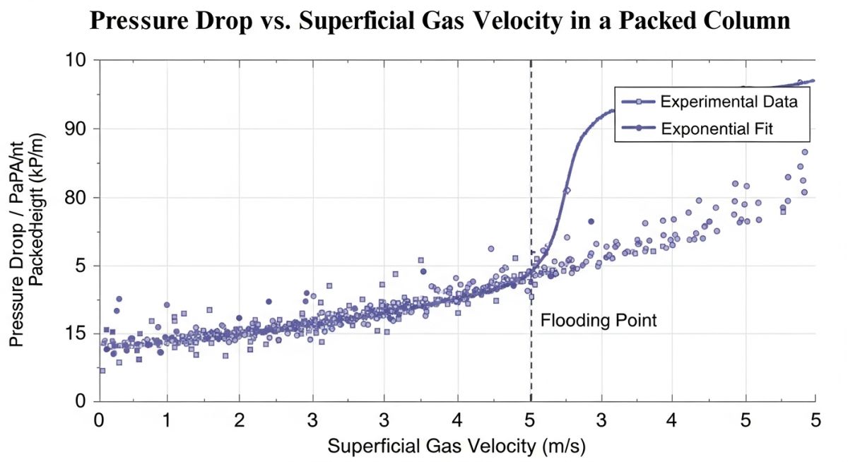
- Tower Pressure Drop Relations
- Turndown Ratio Optimization
- Hydraulic Gradient & Trays
- Tray Types Comparison
Complete Course on
Piping Engineering
Check Now
Key Features
- 125+ Hours Content
- 500+ Recorded Lectures
- 20+ Years Exp.
- Lifetime Access
Coverage
- Codes & Standards
- Layouts & Design
- Material Eng.
- Stress Analysis
Technical Assessment: Tray Hydraulics
Validate your knowledge on flooding in distillation column mechanics.
What occurs when the vapor velocity is too low to support the liquid on a tray?
Understanding Weeping vs. Flooding in Distillation Column Dynamics
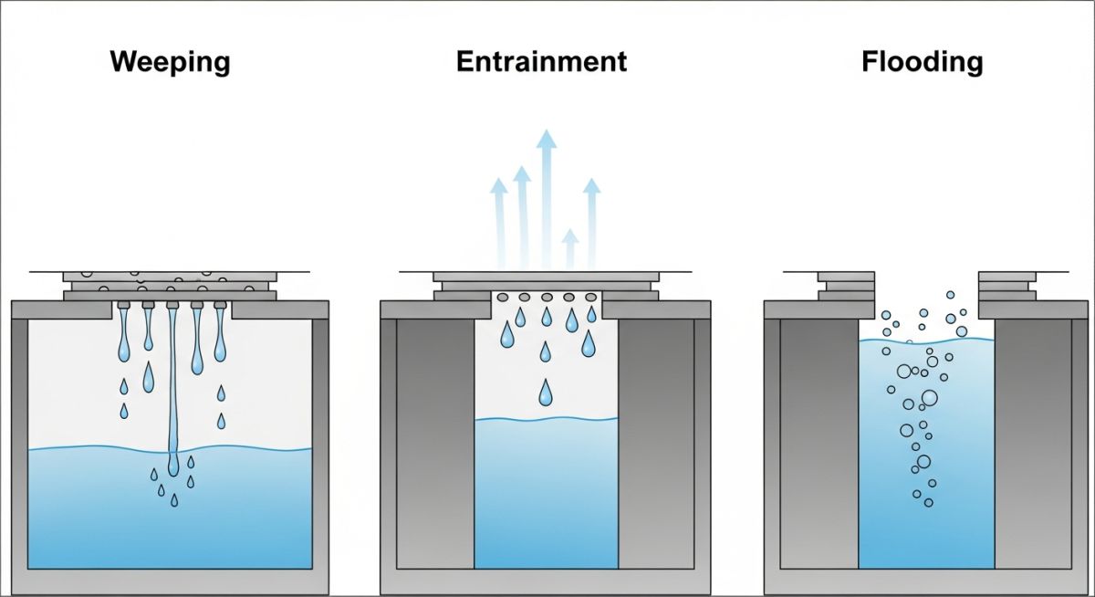
To maintain high separation efficiency, a distillation tray must maintain a stable “froth” zone where vapor and liquid interact. However, when the vapor velocity through the tray perforations (holes) drops below a critical threshold, the kinetic energy of the rising vapor can no longer support the liquid head on the tray. This results in weeping, where liquid leaks through the holes directly to the tray below, bypassing the intended downcomer path.
While minor weeping reduces efficiency, extreme weeping—often called dumping—renders the column non-functional. Conversely, flooding in distillation column operations represents the upper limit of this hydraulic balance. Understanding the “operating window” between weeping and flooding is essential for process engineers, especially when dealing with high turndown requirements. According to the ASME Boiler and Pressure Vessel Code (BPVC) guidelines for internal design, maintaining tray stability is paramount for structural integrity under varying pressure gradients.
The Impact of Entrainment on Flooding in Distillation Column Performance
Entrainment refers to the carryover of liquid droplets by the rising vapor stream to the tray above. While a small amount of entrainment is typical in any mass transfer operation, excessive entrainment recycled back to the upper trays increases the liquid load. This “internal recycle” effectively consumes the column’s capacity.
As the entrainment fraction (often denoted as ‘e’) increases, the column approaches the point of jet flooding. This occurs when the momentum of the vapor is so high that it carries bulk liquid into the tray above, causing a rapid accumulation of liquid and a resulting spike in differential pressure.
Defining the Flooding of Distillation Column: Mechanics and Limits
Flooding is not a single event but a category of hydraulic failures. Broadly, it is defined as the condition where liquid and vapor can no longer pass through the column in a counter-current fashion due to excessive flow resistance. In most industrial scenarios, flooding in distillation column systems is categorized into two main types:
- Jet Flooding: Driven by high vapor velocity, causing liquid carryover.
- Downcomer Backup Flooding: Driven by excessive liquid load or high pressure drop, causing the liquid level in the downcomer to exceed the tray spacing.
Effective column design, as outlined in API Standard 521 for pressure-relieving systems, must account for these flooding limits to prevent overpressure during “blocked outlet” or “fire” scenarios, where vapor generation rates might exceed the hydraulic capacity of the internals.
Primary Causes of Flooding in Distillation Column Operations
Advanced hydraulic analysis identifies that flooding in distillation column systems often originates in the downcomer. When the liquid flow rate exceeds the downcomer’s capacity, or the pressure drop across the tray is too high, liquid backs up until it reaches the tray above.
Loss of Downcomer Seal
Occurs when the liquid level falls below the downcomer edge, allowing vapor to bypass the tray and choke the liquid flow.
Inadequate Clearance
Physical restrictions at the downcomer exit (clearance under the weir) cause high exit velocities and liquid backup.
Pressure Drop (ΔH)
Calculated as ΔH = 0.6 × V2, representing the vapor velocity head that liquid must overcome to descend.
Identifying the Point of Incipient Flooding in Distillation Column
Incipient flood is the precise moment when the column efficiency starts to degrade sharply before a total flood occurs. Engineers utilize ISO 10628 standards for diagrammatic representation of these process flows to ensure control systems can detect this threshold. At this stage, the liquid hold-up on the trays increases exponentially with even minor increases in vapor load.
How to Calculate the Height of Liquid on Tray Deck to Prevent Flooding
To prevent flooding in distillation column units, the total liquid height in the downcomer (Hdc) must remain below the tray spacing. This is calculated by summing the pressure drop across the tray, the liquid head on the tray, and the friction loss through the downcomer clearance.
Critical Formula: Crest Height over Weir
Where GPM is the liquid flow rate. If the total height exceeds 50% of the tray spacing, the risk of incipient flooding becomes critical.
Engineering Comparison: Tray Types vs. Flooding Resistance
Selecting the right internal is a strategic decision governed by ASME B31.3 considerations for process piping and internals. Below is a comparison of common tray types and their hydraulic limits.
| Tray Type | Flooding Limit | Turndown Ratio | Pressure Drop |
|---|---|---|---|
| Sieve Tray | Moderate | 2:1 (Poor) | Low |
| Valve Tray | High | 4:1 to 10:1 | Moderate |
| Bubble Cap | Low | Excellent | High |
🧮 Flooding Risk Estimator (Liquid Head)
Estimate the crest height over the weir to evaluate the risk of flooding in distillation column trays. If the total liquid head exceeds 50-60% of your tray spacing, flooding is imminent.
Enter parameters to check hydraulic stability.
EPCLand YouTube Channel
2,500+ Videos • Daily Updates
Engineering Case Study: Resolving Chronic Flooding
The Challenge
A petrochemical facility operating a C3 Splitter reported a sudden 40% loss in propylene purity whenever the feed rate exceeded 85% of design capacity. Traditional troubleshooting suggested fouling, but the Tower Pressure Drop readings indicated a non-linear spike, symptomatic of flooding in distillation column internals.
The Diagnosis
Gamma scanning revealed that liquid was backing up from Tray 42. Hydraulic audit calculations confirmed the Downcomer Clearance was undersized for the new high-capacity valve trays installed during the last turnaround, leading to Downcomer Backup Flooding.
Technical Solution & Outcome
- Modification: Increased the downcomer clearance by 0.5 inches and increased weir height to maintain the seal.
- Result: The Incipient Flood point shifted from 85% to 108% of design capacity.
- ROI: Purity stabilized at 99.5%, resulting in an estimated $1.2M annual revenue increase due to higher throughput.
Don’t miss this video related to Flooding in Distillation Column

Summary: Master Piping Engineering with our complete 125+ hour Certification Course: ……
Expert Insights: Lessons from 20 years in the field
Beware the “False Flood”: Foaming systems can mimic flooding in distillation column symptoms at much lower vapor velocities. Always check your fluid properties against API 521 foaming tendencies before resizing internals.
Delta P Monitoring: A linear increase in pressure drop is normal; an exponential increase is a red flag. High-fidelity DP transmitters are your best defense against jet flooding damage.
Sub-cooling Effects: Cold reflux can cause localized internal condensation, leading to a sudden surge in vapor flow and incipient flooding further down the column.
Frequently Asked Questions: Flooding & Hydraulics
How do you differentiate between weeping and flooding in distillation column operations?
What is the first sign of incipient flooding?
Why does a high reflux ratio lead to flooding?
Can I increase my column capacity without a total shutdown?
What role does downcomer clearance play in flood prevention?
How does tray spacing impact the flooding limit?
📚 Recommended Resources: Flooding in Distillation Column
Read these Guides


Related posts:
![A mechanical sucker rod pumpjack operating in an oil field at sunset]()
What is Sucker Rod Pump System in Oil Production?
![Piping material engineer reviewing technical specifications on a tablet in an industrial plant.]()
How a Piping Material Engineer Drives Industrial Project Success
![Industrial refinery plant showing various types of static equipment]()
What is Static Equipment? Types and List of Static Equipments
![Side-by-side comparison of industrial process piping and power plant steam piping systems.]()
Differences Between ASME B31.3 and B31.1: B31.3 vs B31.1
![Large industrial steel storage tank under construction with cranes and scaffolding]()
Storage Tank Construction Method Statement: Step-by-Step Engineering Guide
![Cutaway diagram of a globe control valve highlighting the internal valve trim components]()
What is a Valve Trim? Types, Components, and Selection


