Floating Roof Tank Design: Engineering Safety and Efficiency in 2026
Floating Roof Tank Design is the industry-standard solution for storing large volumes of volatile petroleum products while minimizing evaporation losses. In 2026, as environmental regulations tighten globally, the focus has intensified on high-performance rim seals and robust structural buoyancy to ensure emission control for volatile organic compounds (VOC). By allowing the roof to float directly on the liquid surface, this design virtually eliminates the vapor space (ullage), significantly reducing the risk of internal explosions and product degradation.
What is a Floating Roof Tank?
A floating roof tank is a storage vessel where the roof floats directly on the liquid surface, rising and falling with the liquid level. This architecture is primarily used to minimize evaporative losses of high-volatility products like crude oil and gasoline. It consists of a buoyant deck (pontoon or double-deck) and a sealing system that bridges the gap between the roof and the tank shell.
Quick Navigation
Floating Roof Technical Quiz
Question 1 of 51. Which API 650 Appendix governs the design and construction of external floating roofs?
Complete Course on
Piping Engineering
Check Now
Key Features
- 125+ Hours Content
- 500+ Recorded Lectures
- 20+ Years Exp.
- Lifetime Access
Coverage
- Codes & Standards
- Layouts & Design
- Material Eng.
- Stress Analysis
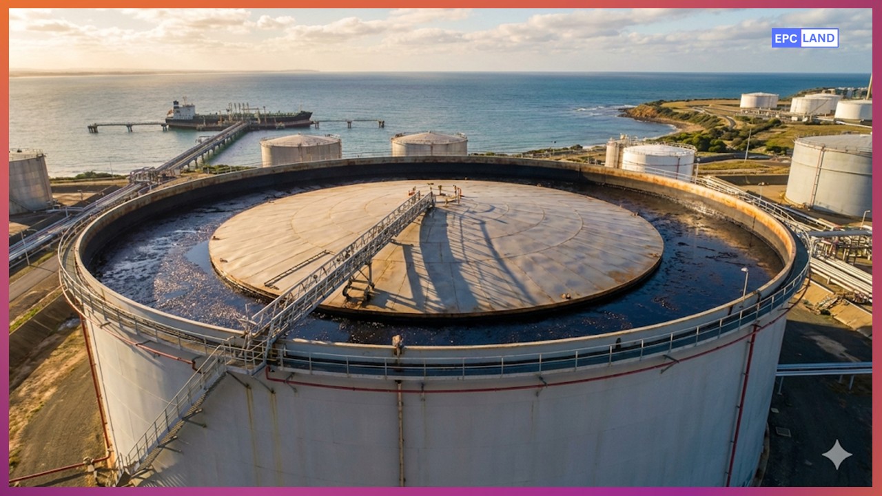
Figure 1: Industrial External Floating Roof Tank (EFRT) layout optimized for 2026 safety standards.
Floating Roof Tank Design: Buoyancy and API 650 Appendix C Requirements
The core objective of Floating Roof Tank Design is to maintain a constant contact between the roof deck and the stored liquid, thereby eliminating the vapor space where hazardous gases accumulate. In 2026, the primary engineering directive for these structures is API 650 Appendix C requirements, which specifically governs external floating roofs. This appendix mandates rigorous calculations for buoyancy, ensuring the roof can support not only its own weight but also the additional loads of accumulated rainwater, snow, and the mechanical components of the seal system.
Structural integrity starts with the “pontoon” or “double-deck” configuration. Pontoon roofs utilize a ring of liquid-tight compartments around the perimeter, providing the necessary displacement to float. For very large tanks (diameters exceeding 60 meters), engineers often specify a double-deck design. This provides a continuous air space between the top and bottom plates, offering superior thermal insulation and increased buoyancy safety factors in the event of a localized puncture.
The Physics of Buoyancy and Load Resistance
A floating roof must be designed to remain buoyant even if two adjacent pontoons are breached (the “Two-Compartment Sinking” criteria). The buoyancy calculation is a critical safety check performed during the Floating Roof Tank Design phase. The net upward force must always exceed the total downward load of the steel, seals, and live environmental loads.
Fb = (V * rho_liquid) – (W_steel + W_seals + W_rain)
Fb = Net Buoyancy Force (must be positive)
V = Total Displaced Volume of the Pontoons
rho_liquid = Density of the stored product (e.g., Crude Oil)
W_steel = Weight of the roof structure
W_seals = Weight of the primary and secondary seals
W_rain = Design water load (typically 10 inches or 250mm)
Strategic Choice: External vs Internal Floating Roof Tanks
When initiating a new project, engineers must weigh the benefits of External vs internal floating roof tanks. While external roofs (EFRTs) are suitable for massive capacities, they are exposed to the elements. Internal floating roofs (IFRTs), which operate inside a fixed-roof tank, offer protection from wind and rain, making them the preferred choice for 2026 environmental compliance in regions with high precipitation or sensitive air quality zones.
| Design Feature | External Floating Roof (EFRT) | Internal Floating Roof (IFRT) |
|---|---|---|
| Standard Reference | API 650 Appendix C | API 650 Appendix H |
| Rainfall Handling | Complex Drainage Systems required | Protected by Fixed Roof |
| Wind Influence | High (Requires Secondary Seals) | Minimal |
| VOC Control | Excellent (with dual seals) | Superior (dual containment) |
| Typical Capacity | Very Large (>50,000 m3) | Small to Medium |
Analysis of Floating Roof Seal Types and Rim Safety

Figure 2: Mechanical shoe seal with secondary wiper for maximum vapor containment.
The rim seal is the most critical mechanical component of the Floating Roof Tank Design. It closes the annular gap between the floating roof and the tank shell, which can vary due to shell out-of-roundness. Modern floating roof seal types are categorized by their mechanical action and material properties.
- Mechanical Shoe Seals: These use a metal plate (shoe) pressed against the tank shell by springs or weights. They are durable and highly effective at managing shell irregularities.
- Liquid-Filled Seals: A flexible tube filled with kerosene or similar liquid that conforms to the shell. These provide an airtight seal but are more susceptible to wear.
- Vapor-Mounted Seals: Installed with a gap between the liquid and the seal fabric. These are generally less effective for emission control for volatile organic compounds (VOC) but are cheaper to install.
Rim Safety and Fire Protection
The rim space is the primary location for lightning-induced fires. In 2026, tank rim seal fire protection has evolved to include automated foam dam systems and linear heat detection cables. These cables are installed around the perimeter of the seal and can trigger a localized extinguishing system within seconds of a thermal event, preventing the spread of fire to the entire liquid surface.
Operational Lifelines: Floating Roof Drainage Systems
For external roofs, floating roof drainage systems are the unsung heroes of buoyancy. Rainwater falling on the roof must be removed to prevent sinking. The most robust designs utilize articulated pipe drains with swivel joints. These pipes are located inside the tank and move with the roof, carrying water from the roof sump to the tank exterior. In 2026, many operators are switching to heavy-duty, multi-layered flexible hoses that are resistant to aromatic hydrocarbons, ensuring that drainage remains functional for decades without internal leaks.
2026 Design Compliance Checklist
- Seal Gap Tolerance: Primary seals must not have gaps larger than 1/8 inch over more than 10% of the circumference.
- Anti-Rotation Cables: Must be installed to prevent the roof from rotating and damaging the rolling ladder or drainage pipes.
- Rolling Ladder: Must be self-leveling and designed for 100% fall protection compliance.
- VOC Monitoring: Installation of automated H2S and VOC sensors at the rim space for early leak detection.
Successfully executing a Floating Roof Tank Design requires a cross-disciplinary approach. From the civil engineering of the foundation to the mechanical precision of the rim seals, every component must work in harmony with the laws of buoyancy and environmental safety. As we move further into 2026, the industry continues to innovate with lighter materials and smarter monitoring systems, ensuring that these massive structures remain both profitable and ecologically responsible.
Case Study: Floating Roof Tank Design Failure Analysis

Figure 3: Articulated roof drainage assembly failure analysis due to swivel-joint seizure.
Project Location
Coastal Crude Terminal, Southeast Asia
Equipment Type
120,000 m3 External Floating Roof Tank
Incident Date
Late Monsoon Season, 2025
Primary Failure
Loss of Buoyancy (Sinking Roof)
Problem Statement: Drainage Obstruction and Roof Sinking
In 2025, a major crude oil terminal experienced a near-catastrophic failure during a high-intensity tropical storm. A massive External Floating Roof Tank (EFRT) began to tilt as the roof deck accumulated over 18 inches of rainwater. Despite the Floating Roof Tank Design being rated for such weather, the internal floating roof drainage systems failed to evacuate the water. The excessive weight caused the roof to submerge on one side, allowing crude oil to spill over the top of the roof deck, creating a severe fire hazard and environmental threat.
The emergency response team had to manually pump water off the roof while balancing the tank’s level to prevent the roof from pinning against the shell. This incident highlighted the vulnerability of large-diameter roofs when their mechanical lifelines are compromised by environmental debris and mechanical fatigue.
Technical Analysis & Root Cause
The post-incident investigation revealed that the primary swivel joints of the articulated drainage pipe had seized due to localized corrosion and “waxy” product buildup that had leaked through a minor gasket failure. Because the joints could not move freely as the roof ascended, the drainage pipe became kinked, completely blocking the flow of rainwater.
Furthermore, the “sump screens” on the roof deck were found to be clogged with wind-blown plastic and organic matter. This prevented water from even reaching the drainage pipes. In this Floating Roof Tank Design, the lack of a secondary or emergency overflow drain meant there was no redundancy once the primary system was obstructed.
Solution & Engineered Result for 2026
The refinery commissioned a complete overhaul of its tank farm engineering standards to align with 2026 best practices. The sinking tank was retrofitted with the following upgrades:
Retrofit Technical Specifications
- Hybrid Drainage System: Replaced the rigid articulated pipes with high-strength, multi-layered flexible hoses that eliminate the need for mechanical swivel joints.
- Redundant Overflows: Installed two additional emergency “bleeder” drains that activate if the water level on the deck exceeds 4 inches.
- Smart Buoyancy Monitoring: Integrated ultrasonic level sensors at four points on the roof to detect “tilting” or “weight imbalance” in real-time, sending alerts to the control room.
- Automated Sump Cleaning: Implemented a quarterly maintenance schedule using high-pressure air-jetting to keep sump screens clear of debris.
The engineered result was a 100% recovery of the tank’s operational integrity. During a similar storm in early 2026, the new floating roof drainage systems performed flawlessly, keeping the roof deck dry and perfectly level. The terminal reported a return on investment (ROI) within one year, as the cost of the retrofit was less than 5% of the projected cleanup and lost-product costs associated with a full roof-sinking event.
Expert Insight:
Floating roof stability is a dynamic equilibrium. In 2026, the move toward flexible hose drains and digital tilt-sensors is no longer optional for high-capacity crude storage—it is the baseline for environmental survival.
EPCLand YouTube Channel
2,500+ Videos • Daily Updates
Frequently Asked Questions
What are the primary API 650 Appendix C requirements for roof design?
How do floating roof seal types impact VOC emissions?
What is the latest tech in tank rim seal fire protection?
How often should floating roof drainage systems be inspected?
Conclusion: Scaling Efficiency in 2026
The evolution of Floating Roof Tank Design represents a triumph of mechanical engineering over environmental volatility. By adhering to API 650 Appendix C and leveraging modern floating roof seal types, terminal operators are significantly reducing their environmental footprint while protecting billions of dollars in liquid assets.
As we look toward the remainder of 2026, the transition toward external vs internal floating roof tanks will be dictated by the global push for “Zero Emission” storage. Whether through the implementation of advanced tank rim seal fire protection or the integration of real-time buoyancy sensors, the industry remains committed to making bulk storage safer, cleaner, and more structurally resilient than ever before.

Related posts:
![High-grade industrial Wing Nut Types and Applications for mechanical assemblies.]()
Wing Nut Types and Applications: The 2026 Engineering Guide
![Industrial Monorail Crane Systems installed in a modern manufacturing plant 2026.]()
Monorail Crane Systems: Design, Types & 2026 Standards Guide
![Lead engineer performing a Factory Acceptance Test FAT on an industrial skid system 2026]()
Factory Acceptance Test FAT: The 2026 Engineering Guide to Zero-Defect Delivery
![Professional engineering workspace showing a Basis of Design document layout for a 2026 project.]()
Basis of Design: How to Write a BOD for Engineering Projects in 2026
![Industrial Flare Knockout Drum Sizing and installation in a refinery relief system.]()
Flare Knockout Drum Sizing: Design & API 521 Standards (2026 Guide)
![Advanced Reboiler Control Systems in a modern petrochemical refinery 2026.]()
Reboiler Control Systems: Engineering Guide to Precision Control 2026


