What is a Flare KOD | Working, Functions, Sizing, and Design of a Knock Out Drum
Imagine an emergency plant blowdown where high-pressure hydrocarbon gases rush toward the flare stack. Suddenly, unseparated liquid droplets are carried into the flame, raining down balls of fire onto the facility—a catastrophic event known as burning rain. This isn’t just a safety drill; it is the direct consequence of a failure in Flare Knockout Drum Sizing.
Whether you are designing for a refinery or a gas processing plant, mastering the vapor-liquid separation physics of a KOD is your primary line of defense. This guide breaks down the complex API 521 calculations into actionable engineering steps to ensure your relief system remains dry and safe.
Key Takeaways
- Flare Knockout Drum Sizing is governed by API 521, focusing on removing droplets larger than 300 to 600 microns.
- Proper liquid holdup volume must accommodate the largest single contingency relief for a minimum of 20 to 30 minutes.
- Selection between horizontal and vertical configurations depends heavily on vapor velocity limits and available plot space.
What is Flare Knockout Drum Sizing?
Flare Knockout Drum Sizing is the engineering process of determining the vessel diameter and length required to reduce vapor velocity, allowing liquid droplets (typically 300-600 microns) to settle out by gravity. Following API 521, sizing ensures sufficient residence time for liquid accumulation during emergency relief events to prevent liquid carryover to the flare.
Founder’s Insight
“In my 20 years of EPC experience, I’ve seen many engineers focus solely on the vapor velocity. However, the real ‘hidden killer’ in Flare Knockout Drum Sizing is the liquid slugs. Never compromise on the 30-minute holdup rule; it’s the only buffer you have when a level transmitter fails during an upset.”
— Atul Singla
Table of Contents
Complete Course on
Piping Engineering
Check Now
Key Features
- 125+ Hours Content
- 500+ Recorded Lectures
- 20+ Years Exp.
- Lifetime Access
Coverage
- Codes & Standards
- Layouts & Design
- Material Eng.
- Stress Analysis
Technical Challenge: Flare Knockout Drum Sizing
Test your knowledge on API 521 standards and KOD design.
Function of a Flare Knockout Drum in Relief Systems
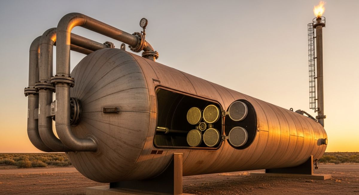
The primary function of a Flare Knockout Drum is to serve as a safety buffer between the process plant’s relief headers and the flare stack. In any industrial facility, relief valves (PSVs) discharge a mixture of gases, vapors, and entrained liquids during overpressure events. If these liquids reach the flare tip, they can cause mechanical damage, extinguish the pilot, or result in “burning rain.” By drastically reducing the velocity of the incoming relief stream, the KOD allows gravity to pull liquid droplets out of the gas phase, ensuring only dry or “lean” gas reaches the combustion point.
Beyond simple separation, these vessels act as a critical storage point. During a massive plant-wide emergency, a Flare Knockout Drum must provide sufficient residence time to hold the cumulative liquid volume from multiple sources. This prevents the liquid level from rising too quickly and being re-entrained into the flare line. According to the American Petroleum Institute (API), maintaining the integrity of this separation is the single most important factor in preventing environmental non-compliance and hazardous ground-level fires.
Critical Design Configurations for Flare Knockout Drum Sizing
When initiating Flare Knockout Drum Sizing, engineers must first select the vessel orientation. The choice between horizontal and vertical configurations is rarely arbitrary; it is driven by the liquid-to-gas ratio and the available footprint within the plant’s battery limits.
- Horizontal Knockout Drums: These are the industry standard for large-scale refineries. The horizontal orientation provides a significantly larger surface area for liquid-vapor disengagement and can handle massive liquid “slugs” much more effectively than vertical units. They are generally preferred when the liquid load is high or when low-pressure drop is a critical design constraint.
- Vertical Knockout Drums: Often utilized in gas processing plants or upstream facilities where liquid loads are relatively low. The vertical configuration occupies less plot space and is easier to equip with high-efficiency mist eliminators. However, they are prone to “slugging” issues if the relief event contains high liquid fractions, as the upward gas velocity can easily re-entrain falling droplets.
API 521 Guidelines for Flare Knockout Drum Sizing and Design
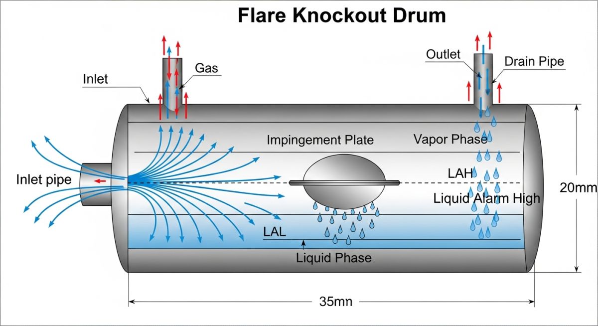
The gold standard for Flare Knockout Drum Sizing is the API 521 standard (Pressure-relieving and Depressuring Systems). The sizing methodology is built upon the principle of terminal settling velocity. The goal is to ensure that the time it takes for a liquid droplet to fall from the top of the vessel to the liquid surface is less than the time it takes for the gas to travel from the inlet to the outlet.
To achieve this, engineers calculate the maximum allowable vapor velocity (Vc) using the Souders-Brown equation. This equation incorporates a “K-factor” (typically ranging from 0.15 to 0.35 for KODs) which accounts for the physical properties of the fluid and the vessel’s internal geometry. In 2026, modern computational fluid dynamics (CFD) are often used to validate these Flare Knockout Drum Sizing calculations, especially for non-standard relief scenarios involving cryogenic or high-viscosity fluids.
Step-by-Step Selection of Droplet Size and Vapor Velocity
The core of Flare Knockout Drum Sizing involves calculating the terminal settling velocity of a liquid droplet. Under API 521, the vessel diameter must be sufficient to ensure the horizontal vapor velocity remains below the terminal velocity of a 300 to 600-micron droplet. This calculation relies on the drag coefficient (Cd) and the Reynolds number of the particle. If the vapor velocity exceeds this limit, droplets are carried overhead into the flare tip, leading to incomplete combustion and hazardous environmental releases.
Liquid Holdup and Residence Time Requirements
Beyond vapor separation, Flare Knockout Drum Sizing must account for emergency liquid storage. High-integrity systems require the vessel to hold the liquid volume from the single largest contingency for 20 to 30 minutes. This “holdup time” provides operators with a critical window to stabilize the plant or initiate an emergency shutdown (ESD) before the drum reaches its High-High Level (LAHH) trip point.
Strategic Locating of the Knockout Drum for Optimal Flow
The physical location of the KOD is as critical as its dimensions. It must be situated at the low point of the flare header to allow for natural slope and gravity drainage of condensed liquids. Furthermore, it should be placed as close to the flare stack as possible—typically within 60 to 100 meters—to minimize the risk of further condensation occurring in the line after the gas has already been processed by the Flare Knockout Drum.
Technical Differences: Flare Knockout Drum Sizing vs Standard Separators
While a standard process separator is designed for continuous operation at steady-state conditions, Flare Knockout Drum Sizing focuses on transient, high-velocity “shock” loads. Standard separators prioritize high-efficiency separation (removing droplets down to 10 microns), whereas a KOD is a safety device designed to handle massive volumes and prevent catastrophic “burning rain” during a total plant power failure or fire.
| Feature | Standard Process Separator | Flare Knockout Drum (KOD) |
|---|---|---|
| Primary Goal | Product purity / Phase recovery | Equipment protection / Safety |
| Droplet Cut-off | 10 – 50 microns | 300 – 600 microns |
| Operating Mode | Continuous / Steady-state | Intermittent / Emergency surge |
| Applicable Code | ASME Section VIII Div 1 | ASME VIII + API 521 |
Preventing the Burning Rain Phenomenon in Flare Knockout Drums
The term “burning rain” refers to unvaporized liquid hydrocarbons exiting the flare tip and igniting in mid-air. This occurs when Flare Knockout Drum Sizing fails to account for peak vapor velocities during a “fire case” relief scenario. To prevent this, engineers must ensure the vessel length-to-diameter (L/D) ratio is optimized, typically between 3:1 and 4:1 for horizontal drums, to maximize the distance available for droplet dropout.
Maintenance and Inspection Requirements for Industrial KODs
Regular maintenance of a KOD is governed by API 510 (Pressure Vessel Inspection Code). Critical focus areas include checking for internal corrosion caused by stagnant acidic condensates and ensuring that the high-level alarms/trips are calibrated and functioning. Because the KOD is an “end-of-line” safety asset, its failure during an emergency can lead to immediate loss of primary containment.
Flare Knockout Drum Sizing Estimator
Quickly estimate the minimum required vessel diameter based on API 521 Terminal Velocity principles (Droplet size: 400 microns).
Case Study: Preventing Burning Rain in a Brownfield Expansion
Project Year: 2026 | Location: Middle East Refinery
The Engineering Challenge
A major refinery expansion increased the total flare header load by 45%. The existing Flare Knockout Drum Sizing was based on 2010 throughput data. During a preliminary safety audit, simulation showed that a “Total Power Failure” scenario would result in vapor velocities exceeding the terminal settling velocity of 600-micron droplets by over 30%.
“The risk of carryover was so high that a relief event would have caused persistent burning rain across the facility’s main pipe rack.”
The API 521 Solution
The engineering team performed a detailed Flare Knockout Drum Sizing re-validation. Instead of replacing the entire vessel, a dual-vessel “Parallel KOD” configuration was designed. By splitting the flow, the vapor velocity was reduced to 2.8 m/s, well within the API 521 safety margin.
- ✔ Installed high-efficiency 316SS Vane Packs to handle fine mist.
- ✔ Increased liquid holdup to 30 minutes for the new peak load.

Figure 1: Parallel KOD installation allowing for 2026 capacity requirements while maintaining 100% droplet dropout efficiency.
Final Outcome
The retrofit successfully passed the 2026 commissioning phase. During a scheduled maintenance trip in Q3, the system handled a localized slug of 150 barrels of condensate without any visible carryover or flame instability at the flare tip.
EPCLand YouTube Channel
2,500+ Videos • Daily Updates
Expert Insights: Lessons from 20 years in the field
Prioritize Vapor Space over Liquid Storage: While liquid holdup is vital, many engineers undersize the vapor space height. In Flare Knockout Drum Sizing, ensuring a minimum of 600mm to 900mm of free vapor space above the High-High Liquid Level (LAHH) is non-negotiable to prevent re-entrainment during peak gas surges.
The 2026 Winterization Standard: For facilities in cold climates, Flare Knockout Drum Sizing must account for high-viscosity liquid accumulation. Without proper steam tracing or heating coils, heavy hydrocarbons can solidify, rendering the gravity-based separation and level instrumentation useless.
Inlet Deflector Integrity: Always specify a high-durability impingement plate or a Schoepentoeter at the inlet. The mechanical energy of a high-pressure relief stream can atomize liquid droplets into a fine mist if not properly dissipated, making standard Flare Knockout Drum Sizing calculations irrelevant.
Authority FAQ: Flare Knockout Drum Sizing & Operations
How do I choose the correct droplet size for Flare Knockout Drum Sizing?
As per API 521, most flare systems are designed to remove droplets between 300 and 600 microns. Droplets smaller than 300 microns are typically consumed in the flare flame without falling out (burning rain), whereas droplets larger than 600 microns pose a significant risk of carryover and flame instability.
What is the minimum liquid holdup time required for a KOD?
Industry best practice for Flare Knockout Drum Sizing dictates a liquid holdup of 20 to 30 minutes based on the largest single relief contingency. This ensures that operators have enough time to manually intervene or for automated pump-out systems to reduce the level before a high-level trip occurs.
When should I use a Vertical KOD instead of a Horizontal one?
Vertical KODs are ideal for applications with low liquid-to-gas ratios or where plot space is extremely limited. However, for most refinery relief headers where high-volume liquid “slugs” are expected, horizontal vessels are preferred due to their superior vapor-liquid disengagement area.
Why did my KOD pass the sizing check but still experience carryover?
This often occurs due to secondary re-entrainment. Even if your Flare Knockout Drum Sizing is correct, high vapor velocities near the liquid surface can “pick up” droplets again. Ensure you have respected the minimum vapor space height (typically 0.6m above LAHH) and installed proper inlet deflectors to dissipate energy.
Can I install a mist eliminator inside a Flare Knockout Drum?
Yes, but with caution. While mist eliminators (vane packs or mesh pads) improve efficiency, they can plug with wax or hydrates, creating a dangerous backpressure on the flare header. If used, they must be designed with bypasses or differential pressure monitoring to comply with API 521 safety mandates.
How does 2026 environmental legislation affect KOD design?
Modern 2026 standards require stricter monitoring of flare combustion efficiency. Because liquid carryover significantly reduces this efficiency, Flare Knockout Drum Sizing is now being scrutinized by regulators. Expect a shift toward larger K-factors and mandatory dual-level redundancy for all new installations.
📚 Recommended Resources: Flare Knockout Drum Sizing

Related posts:
![A mechanical sucker rod pumpjack operating in an oil field at sunset]()
What is Sucker Rod Pump System in Oil Production?
![Piping material engineer reviewing technical specifications on a tablet in an industrial plant.]()
How a Piping Material Engineer Drives Industrial Project Success
![Industrial refinery plant showing various types of static equipment]()
What is Static Equipment? Types and List of Static Equipments
![Side-by-side comparison of industrial process piping and power plant steam piping systems.]()
Differences Between ASME B31.3 and B31.1: B31.3 vs B31.1
![Large industrial steel storage tank under construction with cranes and scaffolding]()
Storage Tank Construction Method Statement: Step-by-Step Engineering Guide
![Cutaway diagram of a globe control valve highlighting the internal valve trim components]()
What is a Valve Trim? Types, Components, and Selection


