What is a Flange Alignment Tool? Applications, Types, and Working Principles
You are on the final hour of a high-stakes refinery turnaround when a 24-inch riser flange refuses to mate. The bolt holes are off by a mere 10mm, but the lateral stress makes manual prying impossible and dangerous. This is where the Flange Alignment Tool becomes the difference between a successful startup and a catastrophic gasket failure. In precision piping, brute force is the enemy of integrity; controlled alignment is the solution.
Key Takeaways
- Understanding the mechanical advantage of tapered expansion in Flange Alignment Tool design.
- Differentiating between mechanical and hydraulic models for various pressure ratings.
- Critical safety protocols to prevent flange face damage and bolt-hole deformation.
What is a Flange Alignment Tool?
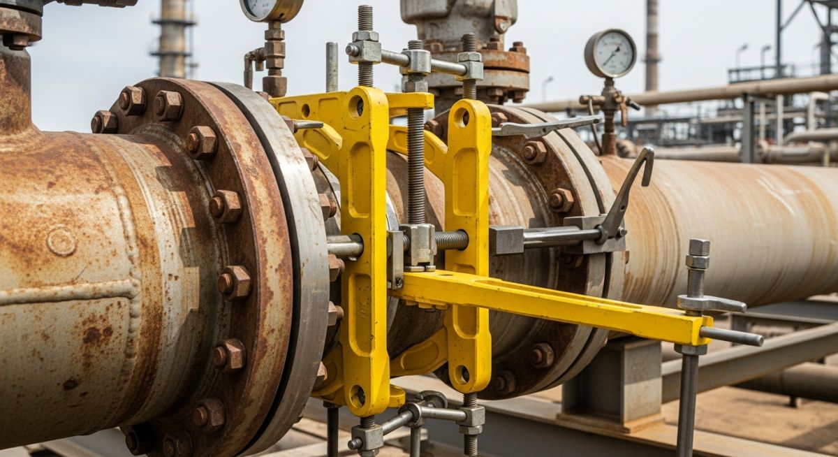
A Flange Alignment Tool is a specialized engineering device used to resolve lateral or rotational misalignment between two pipe flanges. By exerting controlled force through the bolt holes, it brings the flanges into precise concentricity, ensuring safe gasket seating and bolt insertion without damaging the piping system.
Founder’s Insight
“In my 20 years on-site, I’ve seen crews waste hours using ‘come-alongs’ and crowbars. Not only does that risk the technician’s safety, but it also induces secondary stresses into the piping that ASME B31.3 strictly prohibits. A proper Flange Alignment Tool is an investment in joint longevity.”
— Atul Singla
Complete Course on
Piping Engineering
Check Now
Key Features
- 125+ Hours Content
- 500+ Recorded Lectures
- 20+ Years Exp.
- Lifetime Access
Coverage
- Codes & Standards
- Layouts & Design
- Material Eng.
- Stress Analysis
Engineering Knowledge Check
Test your expertise on the Flange Alignment Tool and piping standards.
Question 1 of 5
Which type of misalignment is a Flange Alignment Tool primarily designed to rectify?
Why the Flange Alignment Tool is Critical for Piping Integrity
In industrial piping systems, flange joints are often the weakest point of the pressure envelope. When pipes are fabricated, thermal expansion, pipe weight, or inaccurate support placement can lead to "flange spring"—a condition where the bolt holes of two mating flanges do not align perfectly. Attempting to force these flanges together using standard bolts or drift pins creates localized stress concentrations. A Flange Alignment Tool is utilized to apply a linear, controlled force that shifts the pipe into a neutral position without compromising the metallurgical integrity of the pipe wall or the flange hub.
According to the ASME B31.3 Process Piping Standard, joints must be aligned within specific tolerances to ensure that the gasket is loaded uniformly. If a Flange Alignment Tool is not used to correct rotational or lateral offset, the resulting uneven gasket compression will inevitably lead to fugitive emissions or high-pressure leaks. In hazardous service, such as hydrogen or hydrofluoric acid lines, the precision offered by these tools is not just a convenience—it is a safety mandate.
Mechanical vs. Hydraulic: Comparing Types of Flange Alignment Tools
The selection of a Flange Alignment Tool depends primarily on the pipe size and the force required to overcome the piping's stiffness. For smaller diameter pipes (typically up to 12 inches) with moderate misalignment, a Mechanical Flange Alignment Tool is the industry standard. These tools operate via a screw-thread mechanism where the operator uses a wrench to drive a tapered wing into the bolt hole, gradually pulling the flanges into alignment through mechanical advantage.
Conversely, for heavy-wall piping, large-diameter headers, or high-yield strength materials, a Hydraulic Flange Alignment Tool is required. These units utilize a portable hydraulic pump (manual or electric) to generate up to 25 tons of force. The hydraulic cylinder provides a smooth, jitter-free movement, which is essential when working with sensitive equipment like turbine nozzles or pump casings where sudden mechanical shocks could damage internal bearings.
Industrial Applications of the Flange Alignment Tool
The Flange Alignment Tool is ubiquitous across heavy industries where fluid containment is critical. In the oil and gas sector, these tools are essential for "tie-ins," where a new section of piping is connected to an existing header. Because existing headers have often settled over decades, the alignment is rarely perfect. The tool allows technicians to bring the new flange into the exact plane required for a leak-free seal.
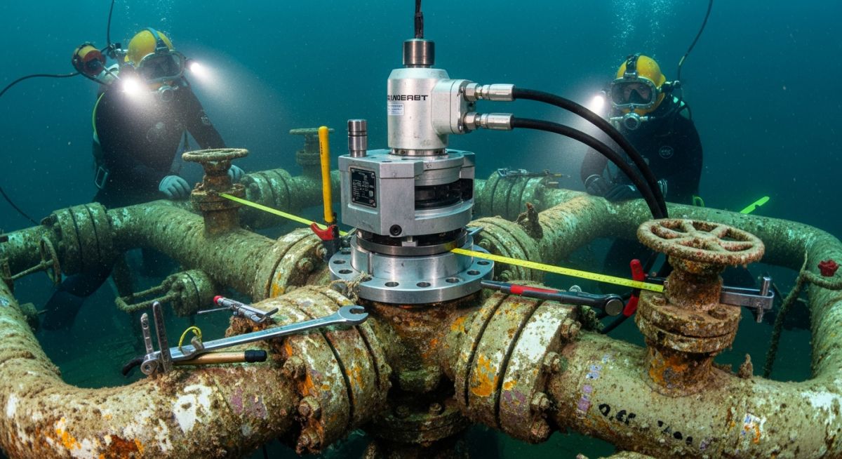
Other critical applications include power plant outages, where condenser lines and steam circuits must be disassembled and reassembled under tight schedules. In marine engineering, Flange Alignment Tools are used in the cramped confines of a ship's engine room, where there is no space for large cranes or external prying equipment. By using a compact alignment tool, engineers can work within the footprint of the pipe itself to achieve 0.5mm precision.
Core Engineering Features of a Professional Flange Alignment Tool
A professional-grade Flange Alignment Tool is engineered to withstand extreme shear forces while maintaining a compact form factor. The most critical feature is the Tapered Wing Design, which allows the tool to enter bolt holes with up to 100% misalignment. High-quality tools are forged from chrome-vanadium or high-tensile alloy steel to prevent "mushrooming" of the tool tip under heavy loads. Furthermore, advanced models feature a "friction-lock" mechanism that prevents the tool from slipping out of the bolt hole during the alignment transition, a common hazard in vertical piping runs.
What’s Inside a Professional Flange Alignment Tool Set?
An engineering Flange Alignment Tool set is typically housed in a ruggedized, weather-resistant case to protect the precision threads and hydraulic seals from the harsh environments of refineries or offshore rigs. A standard mechanical set usually includes the alignment tool body, multiple sizes of tapered bushes to accommodate different bolt hole diameters, and a high-torque ratcheting handle. Hydraulic sets add a 10,000 PSI hand pump, a reinforced hydraulic hose, and a calibrated pressure gauge to monitor the exact force being applied to the piping system.
Technical Specification of Flange Alignment Tools per ASME Standards
When specifying a Flange Alignment Tool, engineers must reference the piping class and material thickness as defined in ASME B16.5 (Pipe Flanges and Flanged Fittings). The tool's capacity must exceed the calculated "spring force" of the pipe. For instance, a schedule 80 carbon steel pipe requires significantly higher alignment force than a schedule 10 stainless steel line of the same diameter.
| Tool Model Type | Max Alignment Force | Bolt Hole Range | Typical Application |
|---|---|---|---|
| Mechanical ATM1 | 1.0 Ton (10 kN) | 16mm - 31.5mm | Small Bore / Low Pressure |
| Mechanical ATM3 | 3.0 Tons (30 kN) | 24mm - 35.5mm | Mid-sized Process Piping |
| Hydraulic ATH9 | 9.0 Tons (90 kN) | 30mm - 54.0mm | Heavy Wall / High Pressure |
| Hydraulic ATH25 | 25.0 Tons (250 kN) | 50mm - 100mm | Large Diameter / Offshore |
Step-by-Step: How to Use a Flange Alignment Tool Safely
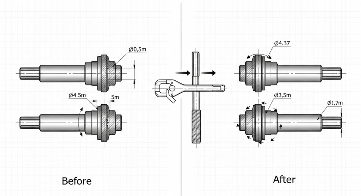
Safe operation of a Flange Alignment Tool begins with identifying the point of maximum misalignment. The tool should be inserted into the bolt hole where the offset is most pronounced. As the operator activates the tool—either by turning the mechanical lead screw or pumping the hydraulic cylinder—the tapered wing extends, making contact with the inner wall of the mating flange's bolt hole.
It is vital to monitor the flange gap during this process; the Flange Alignment Tool should only correct lateral/rotational offset, not be used to pull the flanges together axially (that is the job of a flange puller). Once the holes are concentric, bolts should be inserted into the surrounding holes and hand-tightened before the alignment tool is released. This "pinning" technique ensures the pipe does not spring back into its misaligned state once the tool is removed.
Flange Alignment Force Estimator
Calculate the estimated force required for your Flange Alignment Tool based on pipe parameters.
Recommended Tool: --
Note: This is a simplified structural estimation based on cantilever deflection. Always consult a stress engineer for critical piping systems per ASME B31.3.
EPCLand YouTube Channel
2,500+ Videos • Daily Updates
Engineering Case Study: Offshore Gas Riser Alignment
Project Overview
During a scheduled maintenance turnaround on a North Sea production platform, a 24-inch gas riser flange exhibited significant lateral misalignment following the replacement of a primary isolation valve. Thermal contraction during the depressurization phase caused the piping to "pull away," resulting in a 12mm bolt-hole offset that prevented safe bolt insertion.
- ● Pipe Class: 600# Carbon Steel
- ● Measured Offset: 12mm Lateral / 3-degree Rotational
- ● Constraint: No overhead lifting points for chain blocks.
The Solution: Hydraulic Precision
"Traditional prying methods would have required excessive man-hours and risked damaging the flange face serrations. By deploying a 9-ton hydraulic Flange Alignment Tool, the team achieved concentricity in under 15 minutes."
Technical Outcome
85%
Reduction in Setup Time
Zero
Secondary Stresses Detected
100%
ASME B31.3 Compliance
By utilizing the Flange Alignment Tool, the engineering team avoided the need for "hot work" or structural modifications to the pipe supports. The tool's tapered wing distributed the alignment force evenly across the bolt hole circumference, preserving the metallurgical integrity of the riser material.
Don't miss this video related to Flange

Summary: Master Piping Engineering with our complete 125+ hour Certification Course: ......
Expert Insights: Lessons from 20 years in the field
Never exceed the tool's rated capacity: If a 9-ton hydraulic Flange Alignment Tool isn't moving the pipe, do not use a cheater bar or increase pump pressure. This usually indicates a "locked" piping system where a support or anchor is preventing movement.
Protect the Serrated Face: While the Flange Alignment Tool works through the bolt holes, improper placement can cause the tool body to mar the flange face. Always ensure the tool's reaction point is on the outer diameter or the back of the flange.
Rotational Correction: For severe rotational misalignment, use two Flange Alignment Tools positioned 180 degrees apart. This creates a "couple" force that rotates the pipe much more efficiently than a single point of pressure.
Calibration Matters: In 2026, many high-spec projects require a calibration certificate for the hydraulic gauges used with the Flange Alignment Tool. Ensure your kit is documented to avoid site work permit rejections.
Frequently Asked Questions: Flange Alignment Tool
Can I use a Flange Alignment Tool if the pipe is under pressure?
What is the difference between a flange spreader and a Flange Alignment Tool?
Will a Flange Alignment Tool damage my bolt hole threads?
How do I choose between a mechanical and hydraulic Flange Alignment Tool?
Is it safe to use a Flange Alignment Tool on plastic or fiberglass (GRP) piping?
What is the maximum misalignment a Flange Alignment Tool can fix?
📚 Recommended Resources: Flange
Read these Guides
🎓 Advanced Training


Related posts:
![High-grade industrial Wing Nut Types and Applications for mechanical assemblies.]()
Wing Nut Types and Applications: The 2026 Engineering Guide
![Industrial Monorail Crane Systems installed in a modern manufacturing plant 2026.]()
Monorail Crane Systems: Design, Types & 2026 Standards Guide
![Lead engineer performing a Factory Acceptance Test FAT on an industrial skid system 2026]()
Factory Acceptance Test FAT: The 2026 Engineering Guide to Zero-Defect Delivery
![Professional engineering workspace showing a Basis of Design document layout for a 2026 project.]()
Basis of Design: How to Write a BOD for Engineering Projects in 2026
![Industrial Flare Knockout Drum Sizing and installation in a refinery relief system.]()
Flare Knockout Drum Sizing: Design & API 521 Standards (2026 Guide)
![Advanced Reboiler Control Systems in a modern petrochemical refinery 2026.]()
Reboiler Control Systems: Engineering Guide to Precision Control 2026


