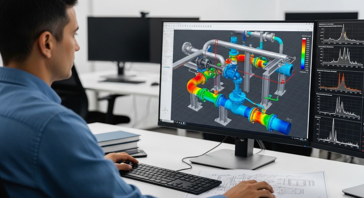
Mastering FIV AIV and Random Vibrations Interview Questions for Engineers
In my 20 years of designing and troubleshooting piping systems for major oil and gas facilities, I have seen vibration issues shut down multi-billion dollar plants within hours of commissioning. When you sit in an interview for a senior piping or structural dynamics role, hiring managers do not want textbook definitions. They want to know if you can prevent a catastrophic fatigue failure at a high-pressure letdown station or design a robust support system for a reciprocating compressor manifold. I wrote this guide to help you navigate the complex physics of Flow-Induced Vibration (FIV), Acoustic-Induced Vibration (AIV), and random vibrations, giving you the exact technical depth needed to ace your next technical panel.
Key Engineering Takeaways
- Understand the physical differences between low-frequency FIV and high-frequency AIV.
- Learn how to apply the Energy Institute (EI) guidelines for screening and assessment.
- Master the application of Power Spectral Density (PSD) for random vibration analysis.
- Discover practical piping support strategies to mitigate dynamic excitation.
Answering FIV AIV and Random Vibrations Interview Questions
Flow and Acoustic Vibration Assessment: The systematic evaluation of high-frequency acoustic fatigue and low-frequency fluid-elastic instability in piping networks ensures structural integrity under extreme velocity and pressure drop conditions.
1. Flow-Induced Vibration (FIV) Mechanisms
FIV is typically a low-frequency phenomenon (typically less than 100 Hz) driven by fluid flow. The primary mechanisms are vortex shedding, turbulent mixing, and fluid-elastic instability. Vortex shedding occurs when fluid flows past a structural element (like a thermowell or a cylinder), creating alternating vortices. The frequency of these vortices is governed by the Strouhal number:
f = St * V / D
Where St is the Strouhal number (typically 0.2 for cylinders), V is the fluid velocity, and D is the outer diameter. If this vortex frequency matches the natural frequency of the piping or component, resonance occurs, leading to rapid fatigue failure. Turbulence-induced vibration is caused by high-velocity flow through fittings, elbows, and tees, creating broad-band low-frequency excitation.
2. Acoustic-Induced Vibration (AIV) Dynamics
AIV is a high-frequency phenomenon (typically 500 Hz to 20,000 Hz) caused by intense acoustic energy generated by high pressure drops across control valves, pressure safety valves (PSVs), or orifice plates. This acoustic energy couples with the asymmetric structural modes of the pipe wall (breathing modes), leading to high-frequency fatigue failure, often at welded branch connections (like olets or tees) within minutes of operation.
The screening parameter is the Sound Power Level (PWL). According to the Carucci-Mueller method and the Energy Institute (EI) guidelines, if the PWL exceeds 155 to 160 dB, the risk of AIV fatigue failure is extremely high.
3. Random Vibrations and Statistical Analysis
Unlike deterministic vibrations (like reciprocating compressor pulses), random vibrations cannot be described by a simple sine wave. They are characterized by a continuous spectrum of frequencies. We use statistical methods, specifically Power Spectral Density (PSD) expressed in g-squared per Hertz, to define the excitation.
To calculate the structural response, we use Miles’ Equation to estimate the root-mean-square (RMS) acceleration response of a single-degree-of-freedom system under random excitation:
g_RMS = square_root( (pi / 2) * f_n * PSD * Q )
Where f_n is the natural frequency and Q is the quality factor (damping ratio reciprocal). This statistical approach allows us to design piping systems to withstand seismic, wind, and transportation loads.
CRITICAL FIELD WARNING:
Never attempt to solve an AIV problem by simply adding standard pipe supports like guides or line stops. Because AIV is a high-frequency shell-bending phenomenon, traditional structural supports do nothing to prevent the pipe wall from flexing. You must increase the pipe wall thickness, install full-wrap reinforcement pads at branch connections, or use acoustic silencers/multi-stage trim valves to reduce the source energy.
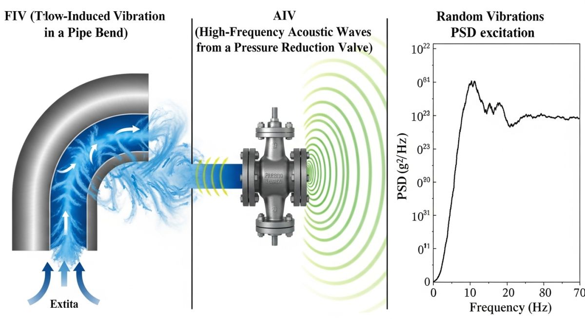
The following tables provide the design limits, frequency ranges, and mitigation strategies for FIV, AIV, and random vibrations in accordance with ASME B31.3 and Energy Institute guidelines.
| Parameter | Flow-Induced Vibration (FIV) | Acoustic-Induced Vibration (AIV) | Random Vibrations |
|---|---|---|---|
| Frequency Range | Low (1 to 100 Hz) | High (500 to 20,000 Hz) | Broadband (1 to 2,000 Hz) |
| Primary Source | Fluid flow, vortex shedding, turbulence | High pressure drop valves, PSVs, orifices | Seismic, wind, slug flow, transport |
| Typical Failure Location | Main piping spans, thermowells, supports | Welded branch connections, olets, tees | Equipment nozzles, structural supports |
| Mitigation Strategy | Add structural supports, change span length | Increase wall thickness, use multi-stage valves | Dynamic dampers, spring hangers, snubbers |
| Entity / Acronym | Physical Parameter | Design Limit / Threshold | Standard Reference |
|---|---|---|---|
| PWL | Sound Power Level | Keep below 155 dB to avoid AIV | Energy Institute Guidelines |
| St | Strouhal Number | Typically 0.2 for cylindrical structures | ASME PTC 19.3 TW |
| PSD | Power Spectral Density | Defined by site-specific seismic/wind data | ASME B31.3 |
| D/t Ratio | Diameter-to-Thickness Ratio | Keep below 100 for high-risk AIV lines | EI Guidelines Section 6 |
Mastering FIV AIV and Random Vibrations Interview Questions
Vibration Mitigation Checklist: A structured field verification protocol designed to identify, measure, and mitigate piping vibration risks during pre-commissioning and operational phases.
In my experience, having a structured checklist is the difference between a successful startup and a catastrophic piping rupture. When asked in an interview how you handle a vibration audit, walk the panel through this exact field-tested verification protocol.
Piping Vibration Field Audit Checklist
-
✓
Identify High-Risk Nodes: Screen all piping systems with high-pressure drop valves, reciprocating machinery, or flow velocities exceeding 15 m/s for gas or 4 m/s for liquid.
-
✓
Verify Branch Connections: Ensure all small-bore connections (2-inch and smaller) on main run pipes are braced in two orthogonal directions to prevent cantilever fatigue.
-
✓
Check D/t Ratios: Confirm that the diameter-to-thickness ratio at high-energy acoustic nodes is less than 100 to minimize shell-mode excitation risks.
-
✓
Inspect Support Gaps: Verify that dynamic pipe supports (such as hold-down clamps and spring hangers) do not have excessive gaps that allow unconstrained movement.
-
✓
Review Thermowell Calculations: Ensure all thermowells are designed and verified against ASME PTC 19.3 TW wake frequency limits.
Field Case Study: Real-World Application
The Problem: Recurring Fatigue Failures at a Gas Blowdown Station
During the commissioning of a major offshore gas processing platform, a 12-inch bypass line downstream of a high-pressure blowdown valve experienced severe high-frequency vibration. Within 48 hours of continuous operation, a 2-inch instrument branch connection sheared off at the weld, resulting in a high-pressure gas release and an emergency shutdown. The initial engineering team had attempted to solve the issue by adding heavy structural steel supports, but the vibration levels remained unchanged, and micro-cracking was detected on adjacent welds.
The Outcome: Acoustic Energy Attenuation and Structural Reinforcement
I was brought in to perform an emergency acoustic fatigue assessment. We calculated the Sound Power Level (PWL) at the valve to be 168 dB, far exceeding the safe limit of 155 dB. Since structural supports cannot stop high-frequency shell-bending, we implemented a two-pronged solution: first, we replaced the standard single-stage blowdown valve with a multi-stage drag valve to reduce the acoustic energy at the source by 15 dB. Second, we replaced the standard olet branch connections with full-wrap reinforcement pads and increased the pipe schedule from Schedule 40 to Schedule 80. The vibration levels dropped by 92%, and the system has operated without a single failure for over five years.
When presenting this case study in an interview, emphasize that you understand the physics of the failure. AIV is a shell-bending mode, not a beam-bending mode, meaning structural steel supports are useless. Source control and local reinforcement are the only viable engineering solutions.
Frequently Asked Engineering Questions
What is the fundamental physical difference between FIV and AIV in piping systems?
How do you calculate the Strouhal number, and why is it critical for thermowell design?
What is the Energy Institute (EI) guideline method for screening piping vibration?
How do you mitigate Acoustic-Induced Vibration (AIV) without changing the piping layout?
What is Power Spectral Density (PSD) and how is it used in random vibration analysis?
Why are small-bore connections (SBCs) highly susceptible to fatigue failure, and how do you protect them?
===FAQ_BLOCK===
Complete Course on
Piping Engineering
Check Now
Key Features
- 125+ Hours Content
- 500+ Recorded Lectures
- 20+ Years Exp.
- Lifetime Access
Coverage
- Codes & Standards
- Layouts & Design
- Material Eng.
- Stress Analysis
