Fired Heaters: Working, Components, Types, and Maintenance Guide
In my 20 years of commissioning refinery equipment, I have stood next to some of the largest thermal giants in the hydrocarbon processing industry. Fired heaters, often referred to as process furnaces, are the beating heart of crude distillation units, vacuum units, and catalytic reformers. Operating these units requires a deep respect for thermodynamics, metallurgy, and fluid dynamics. When you are burning millions of British Thermal Units per hour, even a minor draft imbalance or a slight flame misalignment can lead to catastrophic tube failures, unplanned shutdowns, and millions of dollars in lost production.
Understanding how these systems function, identifying their critical components, and executing rigorous maintenance protocols is what separates a highly efficient plant from an operational hazard. Let us break down the engineering realities of these critical assets, bypassing the high-level summaries to focus on the raw physics, design limits, and field-tested practices that keep these systems running safely.
- Fired heaters transfer up to 60 percent of their heat via radiation in the firebox.
- Draft control is the primary driver of thermal efficiency and structural casing integrity.
- Tube metal temperature monitoring prevents localized coking and subsequent creep rupture.
- Refractory lining degradation is the leading cause of external casing hot spots.
- Regular burner tuning directly reduces nitrogen oxide emissions and fuel consumption.
How Do Fired Heaters Transfer Thermal Energy?
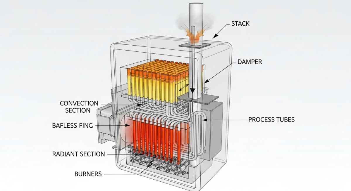
To truly understand a fired heater, we must look at how heat moves from the burner flame to the process fluid. This process is divided into three distinct zones: the radiant section, the shield or shock section, and the convection section.
1. The Radiant Section (The Firebox)
This is the combustion chamber where fuel and air mix and ignite. The tubes in this section are directly exposed to the flame. Heat transfer here is predominantly radiative, governed by the Stefan-Boltzmann law. The radiant heat transfer rate can be calculated using the following relationship:
Where:
• q is the heat transfer rate (Watts)
• sigma is the Stefan-Boltzmann constant (5.67 x 10^-8 W/m^2 K^4)
• epsilon is the effective emissivity of the tube surface and flame (dimensionless)
• A is the radiant surface area of the tubes (square meters)
• Tg is the absolute flue gas temperature (Kelvin)
• Tt is the absolute tube outer wall temperature (Kelvin)
Because the heat transfer is proportional to the fourth power of the absolute temperature, even a small increase in firebox temperature yields a massive increase in heat absorption. This is why controlling the flame pattern is so critical; any flame impingement directly on the tubes can cause localized overheating, exceeding the design Tube Metal Temperature (TMT) limits.
2. The Shield / Shock Section
Located directly above the radiant section, the shield section contains the first two to three rows of the convection bank. These tubes “shield” the rest of the convection section from direct radiation. Consequently, they experience the most severe thermal stress, absorbing both intense radiant heat and high-velocity convective heat from the rising flue gases.
3. The Convection Section
In this upper chamber, heat transfer occurs primarily via convection. The hot flue gases pass over a dense bank of tubes, which often feature extended surfaces (fins or studs) to maximize the heat transfer area. This section recovers the remaining thermal energy from the flue gas before it exits the stack, significantly boosting the overall thermal efficiency of the heater.
Draft and Combustion Air Dynamics
The movement of flue gas through the heater is driven by draft, which is the difference in density between the hot flue gas inside the heater and the cold ambient air outside. The natural draft generated by a stack can be calculated using:
Where:
• h is the stack height (meters)
• g is the acceleration due to gravity (9.81 m/s^2)
• rho_ambient is the density of the ambient air (kg/m^3)
• rho_flue is the density of the hot flue gas (kg/m^3)
To optimize combustion, we must control the excess air. Too little air leads to incomplete combustion, producing carbon monoxide and combustible hazards in the convection section. Too much air carries valuable heat out of the stack, dropping thermal efficiency. For gas-fired systems, I always target 10 to 15 percent excess air, which equates to roughly 2 to 3 percent oxygen in the flue gas.
What Are the Standard Design Parameters?
Designing a fired heater requires balancing thermal duty with metallurgical limits. The table below outlines the typical design parameters I reference during the engineering phase of a project, in compliance with API Standard 560.
| Parameter | Typical Range (Gas Fuel) | Typical Range (Liquid Fuel) | Engineering Significance |
|---|---|---|---|
| Excess Air (%) | 10 – 15 | 15 – 20 | Minimizes fuel consumption and prevents CO formation. |
| Radiant Heat Flux (Btu/hr-ft^2) | 10,000 – 14,000 | 8,000 – 11,000 | Prevents localized tube overheating and fluid cracking. |
| Thermal Efficiency (%) | 75 – 80 (Natural) | 85 – 92 (With APH) | Air Preheaters (APH) recover stack heat to boost efficiency. |
| Arch Draft (in. H2O) | -0.08 to -0.12 | -0.08 to -0.12 | Ensures negative pressure to protect casing refractory. |
| Flue Gas Velocity (ft/s) | 15 – 25 (Convection) | 10 – 20 (Convection) | Balances heat transfer rate with pressure drop limits. |
To ensure long-term mechanical integrity, we must map each physical section of the heater to its corresponding metallurgical standard and inspection code. The matrix below serves as a quick reference for piping and materials engineers.
| Heater Component | Common Materials | Design Code | Inspection Standard | Primary Damage Mechanism |
|---|---|---|---|---|
| Radiant Tubes | ASTM A312 TP347H, 9Cr-1Mo (T9) | API 530 / ASME B31.3 | API 573 | High-temperature creep, carburization, coking. |
| Convection Tubes | Carbon Steel (A106-B), 5Cr-1/2Mo | API 530 / ASME B31.3 | API 573 | Low-temperature sulfur corrosion, oxidation. |
| Refractory Lining | Ceramic Fiber Modules, Castable | API 560 | API 936 | Spalling, mechanical cracking, anchor failure. |
| Tube Supports | HK-40, HP-50 Modified Alloys | API 560 | API 573 | Sigma phase embrittlement, oxidation, sagging. |
| Burner Tips | 310 Stainless Steel, Inconel 601 | API 560 | Manufacturer Std | Tip plugging, thermal erosion, warping. |
How to Inspect Fired Heaters Safely?
Before firing up a heater after a turnaround, a rigorous physical inspection is mandatory. Skipping even a single step can lead to localized hot spots or immediate tube failures. I have developed this field checklist over years of hands-on commissioning to ensure no critical element is overlooked, keeping in line with API RP 573 guidelines.
-
Tube Bowing and Sagging Verification: Measure the deviation of radiant tubes from their original centerline. Any lateral bowing exceeding 1.5 times the tube outer diameter requires engineering evaluation.
-
Refractory Integrity Check: Inspect the firebox walls for missing ceramic fiber modules, cracking in castable refractory, or exposed casing steel. Look for “hot spots” recorded during the previous run.
-
Burner Alignment and Cleanliness: Ensure burner tips are free of carbon deposits and aligned perfectly parallel to the tubes. Misaligned burners cause direct flame impingement.
-
Damper Functionality Test: Manually stroke the stack damper from 0 percent (fully closed) to 100 percent (fully open). Verify that the control room position indicator matches the physical position on the stack.
-
Spring Hanger Load Verification: Check that all external piping spring hangers supporting the inlet and outlet manifolds are within their cold-load design settings.
-
Pilot Igniter and Flame Scanner Check: Clean and test all flame scanners and spark igniters. Verify that the Burner Management System (BMS) correctly registers a flame-out condition.
-
Decoking Verification: If the heater underwent steam-air decoking, perform a final radiograph or ultrasonic thickness (UT) scan on the return bends to confirm complete coke removal.
Field Case Study: Real-World Application
During a routine infrared thermography scan on a Crude Distillation Unit (CDU) charge heater, the operations team detected a severe hot spot on a radiant tube (Tube 14, East Wall). The Tube Metal Temperature (TMT) was reading 685 degrees Celsius, well above the design limit of 620 degrees Celsius. Visual inspection through the peep sights revealed localized flame impingement from Burner #4, which had a partially plugged tip. The high temperature had accelerated internal coking, creating an insulating layer inside the tube that further raised the metal temperature, leading to localized bulging and early-stage creep.
We immediately initiated a controlled load reduction to lower the firebox temperature. Burner #4 was isolated, and its tip was cleaned and realigned to eliminate flame impingement. During the next scheduled short outage, we performed a steam-air decoking operation to clear the internal carbon buildup. Ultrasonic testing (UT) confirmed that the coke layer was completely removed, and a replication test on the bulged tube section verified that the metallurgy had not entered the tertiary creep phase. The heater was safely restarted, and subsequent IR scans showed TMTs had stabilized at a safe 540 degrees Celsius.
My direct recommendation from this event is clear: never rely solely on fixed thermocouples. They only measure temperature at a single point. Implement a weekly infrared thermography program to scan the entire radiant section, catching localized hot spots before they turn into catastrophic tube ruptures.
Frequently Asked Engineering Questions
What causes flame impingement in fired heaters?
How does draft control affect heater efficiency?
What is the difference between cabin and cylindrical heaters?
When should steam-air decoking be performed?
How do you prevent low-temperature sulfur corrosion?
What are the primary causes of tube sagging?
===