Embedded Ring Foundation Design for Wind Turbines and High Towers
In my two decades of heavy industrial and structural design, I have found that designing foundations for multi-megawatt wind turbines and tall communication towers requires moving far beyond traditional gravity spread footings. When you are dealing with towering structures subject to massive cyclic wind shear and overturning moments, relying purely on concrete mass becomes economically unfeasible and structurally inefficient. This is where the embedded ring foundation comes into play as a superior structural solution.
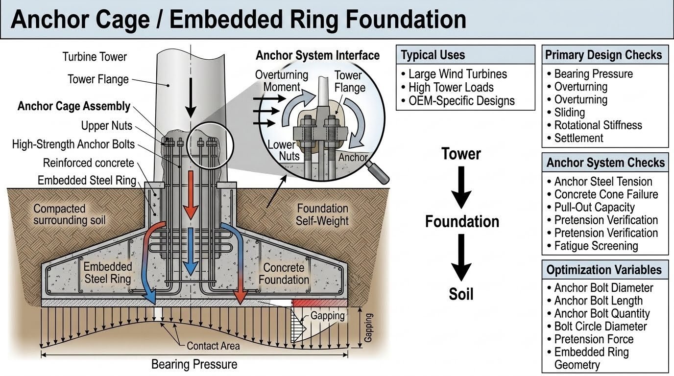
The primary load transfer mechanism relies on an intricate anchor cage assembly that channels extreme structural forces smoothly through the embedded steel ring into the surrounding reinforced concrete pedestal and soil matrix. Mastering this design requires a deep understanding of multi-tiered load paths, precise anchor bolt tensioning, and rigorous fatigue screening in accordance with international design codes.
Key Engineering Takeaways
- Load paths travel sequentially from the turbine tower to the embedded anchor ring, through the concrete foundation body, and finally into the supporting soil.
- Performance is dictated heavily by anchor system design parameters—such as bolt diameter, pretension force, and circle geometry—rather than mass alone.
- Critical failure modes span across geotechnical bearing pressures, concrete cone pull-out, and high-cycle fatigue of steel tendons.
- Optimization relies on balancing bolt circle diameters and embedment lengths to control rotational stiffness and minimize differential settlement.
Embedded Ring Foundation Structural Mechanics
Designing an embedded ring foundation requires evaluating the complex interaction between structural steel elements, high-strength concrete, and the geotechnical continuum. Unlike standard spread footings that rely predominantly on dead weight to resist overturning moments, an embedded ring foundation acts as a moment-resisting rigid frame. The steel anchor cage absorbs high-frequency cyclic bending moments and transfers them uniformly into the massive concrete ring and base slab.
The load path initiates at the wind turbine or tower flange, passing directly into the upper anchor ring assembly. From there, axial and shear loads are distributed down the high-strength anchor rods into the lower anchorage template. The surrounding reinforced concrete mass confines these tension elements, ensuring that load dissipation into the subgrade soil remains within allowable bearing pressure limits.
Primary Global Stability Checks
Global stability analysis forms the first critical phase of the design workflow. Engineers must evaluate four primary failure modes under extreme factored load combinations derived from ASCE 7 and wind turbine design standards such as IEC 61400-1:
- Bearing Pressure: The maximum toe pressure transmitted to the soil must not exceed the allowable geotechnical bearing capacity under eccentric overturning loads.
- Overturning Stability: The stabilizing moment generated by the total foundation mass and overburden soil must maintain a minimum safety factor against the destabilizing wind moment.
- Sliding Resistance: Horizontal shear forces from wind drag must be resisted by base friction and passive earth pressure against the embedded foundation sides.
- Rotational Stiffness: Foundation tilt under service loads must be strictly limited to prevent excessive top-of-tower deflections that could compromise turbine drivetrain alignment.
Critical Design Warning: Edge Pressure Concentrations
In soft or layered soils, eccentric loading can cause a severe triangular or trapezoidal contact pressure distribution. If the resultant load falls outside the kern of the base slab, loss of contact area occurs, rapidly spiking the maximum toe pressure and inducing progressive differential settlement. Always verify that the minimum contact area under ultimate loads remains above zero.
Anchor System Design and Failure Modes
The performance of an embedded ring foundation is governed overwhelmingly by the anchor system rather than the concrete mass. Designing the anchor cage requires checking multiple local failure criteria outlined in ACI 318 Appendix D (or Chapter 17 in recent editions) for anchoring to concrete:
- Anchor Steel Tension: The tensile stress in the anchor bolts under factored loads must remain below the yield strength of the high-strength alloy steel (typically Grade 10.9 or ASTM A615 Grade 75/150).
- Concrete Cone Failure: A tensile load applied through embedded anchor plates can cause a frustum-shaped concrete breakout. Reinforcement must be detailed to intercept potential breakout planes.
- Pull-Out and Bond Capacity: Local bond failure between the steel anchor rod and the surrounding grout or concrete core must be prevented through adequate embedment length and mechanical anchorage devices.
- Pretension Verification: Anchor bolts must be installed with a precisely controlled initial pretension force to eliminate cyclic stress reversals and prevent fatigue crack initiation.
Optimization Variables and Parametric Analysis
Structural optimization of an embedded ring foundation involves fine-tuning several interdependent geometric and material variables to achieve a cost-effective and safe design. Engineers typically adjust the following parameters during finite element modeling:
- Anchor Bolt Diameter and Quantity: Increasing bolt diameter enhances tensile capacity, but spacing rules must be respected to avoid overlapping concrete breakout cones.
- Bolt Circle Diameter: Expanding the bolt circle increases the internal lever arm, drastically reducing peak anchor bolt tension forces under overturning moments.
- Embedment Length: Longer embedment improves bond transfer and increases the concrete cone breakout resistance, though it increases material and excavation costs.
- Embedded Ring Geometry: Modifying the stiffness and thickness of the structural steel embedding ring ensures smooth stress diffusion into the surrounding concrete pedestal.
Ultimately, successful embedded ring foundation design bridges advanced geotechnical mechanics with precise structural detailing. By accounting for high-cycle fatigue, precise pretensioning, and rigorous code compliance, engineers ensure decades of reliable, maintenance-free operation for the world’s tallest energy infrastructure towers.
Advantages
- Superior Moment Resistance: Effectively handles massive overturning moments from tall structures through an expanded internal moment arm.
- Reduced Footprint: Requires significantly less total concrete mass compared to conventional gravity spread footings for equivalent tower heights.
- High Fatigue Tolerance: Controlled anchor bolt pretensioning minimizes stress range fluctuations under cyclic wind loading.
- Precise Alignment: Rigid upper and lower anchor templates allow exact geometric positioning of tower connection flanges during concrete pours.
- Optimal Material Usage: Leverages high-strength structural steel and prestressed tendons where tensile stresses dominate.
Disadvantages
- High Installation Precision: Demands strict dimensional tolerances during anchor cage assembly to prevent fit-up issues with tower sections.
- Complex Detailing: Requires advanced 3D finite element modeling to analyze congestion of reinforcing steel and anchor templates.
- Inspection Challenges: Embedded portions of anchor bolts and internal steel rings are largely inaccessible for non-destructive testing post-pour.
- Specialized Equipment: Requires heavy-duty hydraulic tensioning tools and calibrated torque equipment for proper pretensioning verification.
- Cost Sensitivity: High-strength alloy steel and precision fabrication templates increase initial material procurement expenses.
Onshore Multi-Megawatt Wind Turbines
Modern multi-megawatt wind turbines generate extreme cyclical overturning moments that conventional gravity foundations struggle to resist economically. Embedded ring foundations provide the high rotational stiffness and fatigue-resistant anchor cage design required to secure tall tubular steel towers in variable soil conditions.
Telecommunication and Transmission Towers
Self-supporting lattice and monopole communication towers subject to high wind drag and seismic shear forces benefit immensely from embedded ring systems. The compact footprint fits within restricted site boundaries while anchoring high-capacity base plates securely against uplift.
Offshore Transition Pieces and Jackets
In marine environments and offshore transition structures, embedded ring connections tie heavy-wall steel monopiles to specialized transition platforms. These joints must withstand severe wave slam, current drag, and continuous dynamic loading without losing preload in the fastener assembly.
Industrial Flare Stacks and Chimneys
Industrial flare stacks and refractory-lined chimneys experience intense thermal gradients and wind-induced vortex shedding vibrations. Embedded ring foundations offer the necessary structural rigidity to limit lateral sway and protect the base anchorage from fatigue failure over decades of continuous operation.
Embedded Ring Foundation Design Parameters and Limit States
Designing an embedded ring foundation requires careful balancing of mechanical properties, geometric variables, and geotechnical boundary conditions. In my professional practice, I rely heavily on standardized parameters set forth by ASCE and ACI to establish safe operational limits. The engineering data table below outlines the primary design variables, standard calculation symbols, typical industrial ranges, and governing code references that dictate structural performance under extreme wind turbine loading cycles.
Each parameter directly influences the load transfer mechanism from the steel tower shell down through the embedded anchor cage into the reinforced concrete body and underlying soil. Review these threshold values carefully to ensure your finite element models and manual calculation sheets align with recognized industry benchmarks for fatigue resistance and geotechnical stability.
| Design Parameter | Symbol & Units | Typical Range | Governing Code / Standard |
|---|---|---|---|
| Anchor Bolt Diameter | d_b (mm / in) | 36 mm to 75 mm | ASTM A615 / ASTM A354 |
| Bolt Circle Diameter | D_bc (m / ft) | 3.5 m to 6.5 m | ASCE 7-22 Wind Loads |
| Target Pretension Force | T_pre (kN / kips) | 50% to 70% of Yield | ISO 19901-4 / AISC 360 |
| Concrete Compressive Strength | f’_c (MPa / psi) | 35 MPa to 55 MPa | ACI 318-19 Chapter 17 |
| Embedded Ring Plate Thickness | t_ring (mm / in) | 40 mm to 100 mm | ASME BPVC / AWS D1.1 |
| Rotational Foundation Stiffness | K_phi (MN-m/rad) | 1.0e4 to 5.0e4 MN-m/rad | DNV-ST-0126 |
Note: Values above represent nominal commercial wind turbine configurations. Site-specific geotechnical investigations often necessitate adjustments to ring thickness and embedment depth.
Technical Mapping & Specifications Matrix
To maintain absolute design rigor across multidisciplinary engineering teams, structural entities must be systematically mapped against physical phenomena and testing standards. In this matrix, I have structured the core components of an embedded ring foundation system, identifying their primary analytical functions, material designations, and associated failure modes.
This structured matrix serves as a vital cross-reference during design reviews, structural audits, and finite element validation exercises. By understanding how individual hardware items interact with mass concrete and subgrade soil layers, engineers can eliminate costly oversights in structural detailing.
| Structural Entity | Acronym / Code | Primary Physical Function | Governing Failure Mode |
|---|---|---|---|
| Embedded Steel Ring | ESR / ASTM A572 | Transfers tower overturning moment directly into foundation concrete | Local yielding and plate buckling under extreme shear |
| Anchor Cage Assembly | ACA / ASTM A354 | Provides continuous post-tensioned clamping force for the tower flange | Fatigue cracking and thread stripping at cyclic tension peaks |
| Mass Concrete Body | MCB / ACI 318 | Provides ballast weight and distributes concentrated loads to soil | Concrete cone breakout and excessive soil bearing pressure |
| Grout Layer Interface | GLI / ASTM C1107 | Levels base flange and ensures uniform stress transfer to concrete | Crushing, micro-cracking, and fatigue degradation under rocking |
| Geotechnical Subgrade | GS / ASCE 7 | Resists base sliding, overturning moments, and vertical settlement | Soil shear failure, excessive rotation, and differential settlement |
Reference: Entity interactions are modeled numerically using finite element software complying with DNV-ST-0126 validation criteria for wind turbine support structures.
Site Verification Checklist for Embedded Ring Foundations
Field execution of an embedded ring foundation requires rigorous quality control procedures. In my site engineering experience, overlooking minor installation tolerances during anchor cage placement or concrete pouring can lead to catastrophic fatigue failures during turbine operation.
Use this comprehensive site verification checklist before, during, and after construction to ensure strict compliance with ACI 318 and ASCE construction standards. Every checkpoint must be signed off by a certified quality control engineer.
Pre-Pour & Post-Installation Verification Protocol
- [ ] Anchor Cage Alignment: Verify that the anchor bolt circle diameter and azimuth orientation match OEM drawings within a strict tolerance of plus or minus 2 millimeters.
- [ ] Embedded Ring Levelness: Check the embedded steel ring elevation using high-precision optical levels to ensure maximum out-of-levelness does not exceed 1 millimeter across the entire flange diameter.
- [ ] Tendon & Bolt Cleanliness: Inspect all anchor bolt threads for debris, rust, or mechanical damage prior to concrete placement and apply approved protective grease or caps.
- [ ] Concrete Mix Design Verification: Confirm that the supplied mix meets ACI 318 specifications for target compressive strength (f’_c) and low heat of hydration to prevent thermal cracking in mass elements.
- [ ] Vibration and Consolidation: Ensure internal mechanical vibrators are used correctly around the embedded ring assembly to eliminate honeycombing without displacing the anchor cage.
- [ ] Curing Temperature Monitoring: Install thermocouples within the mass concrete core to verify that the temperature differential between the core and surface does not exceed 20 degrees Celsius.
- [ ] Post-Tensioning Torque Verification: Calibrate hydraulic tensioning equipment and verify that final bolt pretension forces meet design engineering specifications before turbine erection commences.
Compliance Rule: Any deviation exceeding allowable installation tolerances requires formal structural re-evaluation and written approval from the principal design engineer before loading.
Field Case Study: Real-World Application
In a recent 3.6-megawatt onshore wind farm project situated on a complex coastal ridge, our engineering team encountered severe dynamic load amplification and cyclic fatigue issues during initial wind turbine commissioning. The embedded ring foundation experienced excessive rotational rocking, triggering premature micro-cracking in the upper grout layer and cyclic loosening of several anchor bolts.
This field case study outlines the diagnostic investigation, root-cause identification, and engineered remediation protocol implemented to restore structural integrity and ensure long-term operational safety in accordance with ASCE and DNV guidelines.
Problem Analysis: Excessive Rocking and Pretension Loss
During peak wind gusts exceeding 25 meters per second, the tower base displayed lateral deflections exceeding allowable OEM operational thresholds due to combined subgrade compliance and inadequate initial bolt pretensioning.
- Initial anchor bolt pretension forces had relaxed by 18 percent within the first six months of operation.
- Subgrade soil stiffness was lower than anticipated in the preliminary geotechnical report, increasing rotational foundation compliance.
- Cyclic bending moments induced high local compressive stresses at the concrete-grout interface, leading to localized crushing.
- Dynamic amplification factors under wind turbulence caused stress reversals in the upper anchor cage region, initiating micro-fatigue cracking.
Solution Outcome: Retrofit and Rigorous Monitoring
We executed a comprehensive engineering remediation plan that successfully stabilized the turbine foundation and eliminated excessive dynamic movement.
- Hydraulic retensioning of all anchor bolts to 70 percent of ultimate yield strength using calibrated multi-jack tensioners.
- Injection of high-strength, non-shrink epoxy grout into deteriorated interface zones to restore uniform load transfer across the embedded ring.
- Installation of continuous optical strain gauges and accelerometers to monitor long-term bolt tension retention and foundation rotation in real-time.
- Establishment of a mandatory annual torque inspection schedule compliant with ASTM maintenance standards.
Engineering Recommendation: For future installations in similar geotechnical environments, engineers should specify higher initial pretension margins, mandate higher-grade epoxy grouts, and conduct rigorous finite element fatigue screening during the preliminary design phase.
Frequently Asked Engineering Questions
What is the primary load transfer mechanism in an embedded ring foundation?
- Tower flange forces channel axial compression and tension directly into the upper ring anchor bolts.
- The embedded steel ring acts as a rigid moment transfer medium, eliminating concentrated corner crushing on the concrete.
- Load dispersion follows a diagonal compressive strut path down to the foundation base slab and subgrade interface according to ACI 318 guidelines.
How do you prevent concrete cone failure in high-capacity anchor cages?
- Increase embedment depth beyond the critical breakout cone projection calculated via ASME and ACI provisions.
- Deploy dedicated supplementary skin reinforcement and hairpins specifically detailed to intercept potential breakout planes.
- Incorporate headed anchor studs or thick anchor plates at the embedded base to increase the projected failure surface area.
Why is rotational stiffness critical for modern wind turbine foundation design?
- Excessive foundation rotation amplifies dynamic amplification factors at the tower top, accelerating mechanical wear.
- Stiffness is heavily influenced by the anchor bolt circle diameter and effective pretension force rather than concrete volume alone.
- Design calculations must account for soil-structure interaction and subgrade modulus degradation under cyclic fatigue loading.
What installation tolerances apply to embedded ring anchor assemblies?
- Anchor bolt verticality must be maintained within tight angular limits (typically less than 1:100) to prevent eccentric bending stresses.
- Bolt circle diameter and radial spacing require laser-verified template checks prior to concrete pouring.
- Thread protection and corrosion mitigation must be strictly enforced during construction phases to preserve high-strength steel integrity.
How is fatigue screening performed for embedded anchor systems?
- Stress range calculations use Palmgren-Miner linear damage accumulation models combined with site-specific wind scatter diagrams.
- Adequate initial pretension force is verified to ensure anchor bolts never experience complete stress relaxation or joint separation under peak gust events.
- Detailing must avoid sharp geometric notches and stress concentration points in welded ring segments.
Field Recommendation
- If site geotechnical investigations reveal low subgrade stiffness or high compressible layers, choose a wider bolt circle diameter and increased anchor embedment length to enhance rotational stiffness rather than simply expanding the concrete base slab volume.
- When reviewing OEM foundation drawings, always verify that the specified anchor bolt pretension force exceeds the maximum calculated cyclic tensile range to prevent joint separation and catastrophic fatigue failure in high-wind environments.
- During concrete placement around complex anchor cages, mandate high-frequency internal vibrators and self-consolidating mix designs with strict aggregate size limits to eliminate honeycombing and ensure uncompromised bond stress transfer along the embedded ring perimeter.
- For offshore or corrosive onshore installations, mandate multi-layer epoxy coating systems and impressed current cathodic protection on all exposed anchor hardware and embedded ring interfaces to safeguard structural integrity against long-term environmental degradation.
- Prioritize laser-based surveying templates over traditional wooden templates during cage assembly to maintain sub-millimeter bolt alignment tolerances, directly preventing severe secondary bending moments during tower mating operations.
Complete Course on
Piping Engineering
Check Now
Key Features
- 125+ Hours Content
- 500+ Recorded Lectures
- 20+ Years Exp.
- Lifetime Access
Coverage
- Codes & Standards
- Layouts & Design
- Material Eng.
- Stress Analysis
