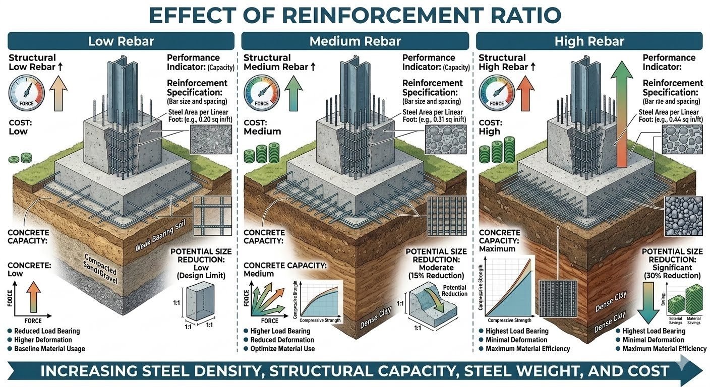
Effect of Reinforcement Ratio on Structural Capacity and Size Reduction
In my two decades of reviewing heavy industrial and structural design packages, I have consistently observed that the steel reinforcement ratio remains the single most influential variable governing member cross-sectional dimensions and cost efficiency. When we evaluate structural elements under heavy bending and axial loads, the precise distribution of steel area per linear foot dictates whether a concrete section operates in a tension-controlled, transition, or compression-controlled domain.
Understanding the distinct thresholds between low, medium, and high rebar configurations allows lead engineers to optimize material usage without compromising safety margins. This technical review examines how shifting from 0.20 sq in/ft to 0.44 sq in/ft impacts ultimate moment capacity, deflection characteristics, and member sizing potential.
Key Engineering Takeaways
- Low Rebar (0.20 sq in/ft): Delivers minimal cost alongside low structural capacity and negligible size reduction limits.
- Medium Rebar (0.31 sq in/ft): Achieves balanced performance with a moderate 15 percent potential cross-sectional size reduction.
- High Rebar (0.44 sq in/ft): Maximizes load-bearing and material efficiency, unlocking a substantial 30 percent potential size reduction.
- Economic Parallel: Increasing steel density mirrors concrete strength upgrades by directly trading material volume for spatial compactness.
Effect of Reinforcement Ratio Mechanics and Design Limits
The structural reinforcement ratio, denoted mathematically as rho (rho = As / (b · d)), dictates the percentage of total cross-sectional area dedicated to tensile steel reinforcement. In my design practice, controlling this parameter is essential for satisfying both ultimate limit states (ULS) and serviceability limit states (SLS). As we scale steel density from low to high configurations, the internal couple formed by the concrete compressive block and the tensile steel shifts significantly.
To evaluate the true impact of rebar distribution, we must analyze three distinct operating tiers defined by steel area per linear foot:
- Low Rebar Configuration (0.20 sq in/ft): Operates near minimum reinforcement limits (ACI 318 Section 9.6). It yields a shallow neutral axis depth, resulting in low overall structural capacity, higher deflection under service loads, and virtually zero potential for member size reduction.
- Medium Rebar Configuration (0.31 sq in/ft): Represents a balanced industrial baseline. This configuration provides moderate concrete capacity, controls flexural cracking within allowable crack width parameters, and enables a moderate 15 percent potential reduction in member cross-sectional dimensions.
- High Rebar Configuration (0.44 sq in/ft): Pushes steel density toward congestion limits. It maximizes ultimate load-bearing capacity, minimizes long-term creep and deflection, and unlocks a maximum 30 percent potential size reduction, conserving valuable footprint in congested process units.
Critical Design Warning: Steel Congestion and Bond Failure
Exceeding practical reinforcement ratios in high rebar configurations without proper bar spacing risks severe honeycombing and loss of bond strength. Ensure clear spacing complies with ACI 318 minimum bar spacing rules (greater than db, 1 inch, or 1.33 times the maximum aggregate size) to prevent structural failure during concrete consolidation.
From a mathematical perspective, nominal flexural strength (Mn) is calculated using the internal lever arm between the resultant compressive force in the concrete (C = 0.85 · f’c · a · b) and the tensile force in the steel (T = As · fy). When we increase the reinforcement ratio from low to high:
- The tensile force (T) increases proportionally with steel area (As).
- The depth of the equivalent rectangular stress block (a) increases to maintain internal equilibrium (a = (As · fy) / (0.85 · f’c · b)).
- The neutral axis depth (c = a / β_1) deepens, reducing the net tensile strain in the extreme tension steel and pushing the section closer to the tension-controlled strain limit of 0.005.
This direct interaction explains why high rebar configurations achieve superior structural performance. By concentrating high tensile capacity into a smaller concrete profile, structural engineers achieve significant dimensional savings. However, this demands rigorous detailing to ensure ductility is maintained and brittle compression failures are strictly avoided.
Advantages of Optimized Reinforcement
- High Rebar Efficiency: Achieves up to a 30 percent reduction in structural member dimensions, saving valuable plant footprint.
- Cost Flexibility: Low rebar configurations (0.20 sq in/ft) minimize initial material expenditure for lightly loaded secondary structures.
- Deflection Control: Medium and high rebar densities significantly restrict long-term creep and immediate elastic deflections under heavy industrial loads.
- Crack Mitigation: Increased steel area distributes tensile stresses more evenly, reducing maximum crack widths in aggressive chemical environments.
- Load Capacity Scaling: Predictable linear scaling allows engineers to tailor member capacity precisely to specific operational load envelopes.
Disadvantages & Technical Risks
- Congestion Risks: High rebar configurations (0.44 sq in/ft) create severe reinforcement congestion, complicating concrete placement and vibration.
- Ductility Reduction: Higher steel ratios reduce net tensile strain, shifting the section closer to a brittle compression-controlled failure mode if over-reinforced.
- Material Cost Escalation: High rebar density substantially increases raw steel material procurement and fabrication expenses per linear foot.
- Low Capacity Limits: Low rebar configurations severely restrict structural capacity and eliminate potential size reduction, requiring bulkier concrete sections.
- Thermal Cracking: Dense reinforcement webs increase restraint against early thermal shrinkage, raising the risk of restrained concrete cracking.
Heavy Pipe Rack Foundations
Industrial pipe racks carrying large-diameter process headers require high structural capacity to resist sustained dead loads, thermal expansion friction, and seismic forces. Utilizing a high rebar configuration (0.44 sq in/ft) enables structural engineers to reduce foundation pad footprints by up to 30 percent, fitting complex underground utility layouts without spatial interference.
Secondary Containment Bunds
Chemical storage tank containment walls experience moderate hydrostatic pressures and thermal cycling. A medium rebar configuration (0.31 sq in/ft) provides an optimal balance between crack control and cost, limiting crack widths to prevent chemical seepage while avoiding the severe reinforcement congestion associated with higher steel ratios.
Lightweight Equipment Pedestals
Minor pump and instrument skids with minimal static loads do not warrant heavy steel investments. Applying a low rebar configuration (0.20 sq in/ft) satisfies minimum temperature and shrinkage steel requirements under ACI 318, achieving low structural capacity at minimal cost where spatial reduction is not required.
Vibration-Prone Compressor Foundations
Reciprocating compressors generate dynamic vibrational loads that require rigid, high-mass concrete blocks combined with dense internal reinforcement. High rebar configurations restrict microscopic deflections and prevent fatigue cracking at anchor bolt assemblies, ensuring long-term alignment stability under continuous cyclic operation.
Elevated Concrete Transfer Slabs
Multi-story industrial modules often rely on thick transfer slabs to redistribute column loads across irregular grid lines. High reinforcement ratios are mandatory in these high-shear zones to achieve maximum load-bearing efficiency, preventing punching shear failures and enabling sleek architectural profiles despite massive tributary loads.
