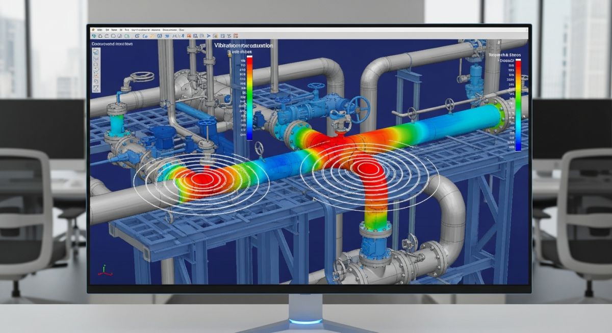
Master Your Next Technical Interview With These Dynamic Pipe Stress Analysis Interview Questions
In my 20+ years of piping engineering experience, I have sat on both sides of the interview table. I can tell you that general static stress questions are easy to pass, but the real filter for senior roles lies in dynamic analysis. When a plant experiences a steam hammer or reciprocating compressor vibration, static calculations are useless.
Interviews for senior stress engineers focus heavily on your physical understanding of mass, stiffness, and damping. This guide compiles the exact technical questions, mathematical concepts, and code requirements I use to evaluate candidates.
- Master the core differences between static and dynamic piping behavior.
- Understand how to calculate natural frequencies and dynamic amplification factors.
- Learn to explain complex transient events like water hammer and slug flow.
- Discover how to apply ASME B31.3 and API 618 standards to dynamic problems.
Mastering Dynamic Pipe Stress Analysis Interview Questions
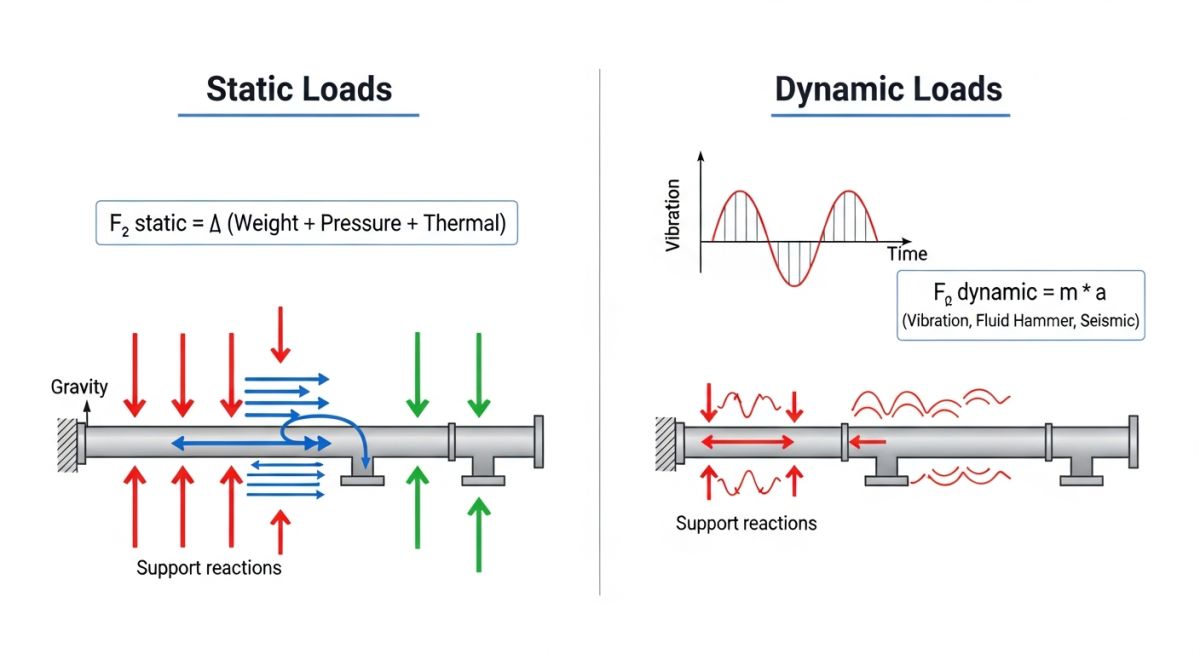
To excel in dynamic stress analysis, you must understand that dynamic loads are time-dependent. Unlike static loads where force is constant, dynamic forces change in magnitude, direction, or point of application over time. This introduces inertial forces and damping effects that require solving the governing differential equation of motion.
The Governing Equation of Motion
Every dynamic piping problem is governed by the classic second-order differential equation:
M * x”(t) + C * x'(t) + K * x(t) = F(t)
Where M represents the mass matrix (including pipe, fluid, insulation, and components), C is the damping matrix, K is the stiffness matrix of the piping system and its supports, and F(t) is the time-varying external force vector. The terms x”(t), x'(t), and x(t) represent acceleration, velocity, and displacement respectively.
Modal Analysis and Natural Frequency
In my project reviews, I always ask candidates to explain modal analysis first. Modal analysis determines the natural frequencies and mode shapes of the piping system. The undamped free vibration natural frequency (fn) of a single degree of freedom system is calculated as:
fn = (1 / (2 * pi)) * square_root(K / M)
If an external excitation frequency matches one of these natural frequencies, resonance occurs. This leads to massive displacement amplification, high cyclic stresses, and eventual fatigue failure.
Understanding the Dynamic Amplification Factor
The Dynamic Amplification Factor (DAF) is the ratio of dynamic deflection to static deflection. It is a function of the frequency ratio (r = excitation frequency / natural frequency) and the damping ratio (zeta):
DAF = 1 / square_root((1 – r^2)^2 + (2 * zeta * r)^2)
When r approaches 1 (resonance), the DAF is limited only by damping. For typical piping systems, damping is low (usually 2% to 5% of critical damping), meaning the DAF can easily reach values of 10 to 25, leading to rapid mechanical failure.
Preparing for Dynamic Pipe Stress Analysis Interview Questions
To systematically evaluate dynamic problems, we classify loads based on their time-history profiles. The table below outlines the primary dynamic loads encountered in industrial process plants, their mathematical nature, and standard mitigation strategies.
| Load Type | Mathematical Profile | Typical Source | Mitigation Strategy |
|---|---|---|---|
| Harmonic / Steady-State | Continuous sinusoidal excitation | Reciprocating compressors, pumps | Stiffness tuning, analog bottles, pulsation dampeners |
| Transient / Impulsive | Short duration, high amplitude shock | Water hammer, relief valve pop | Snubbers, fast-acting valves, rigid struts |
| Random / Stochastic | Non-periodic, statistical distribution | Wind, seismic ground motion | Guide supports, limit stops, sway braces |
This matrix maps critical dynamic parameters to their corresponding engineering standards, software inputs, and physical significance.
| Parameter / Entity | Acronym | Physical Significance | Governing Standard |
|---|---|---|---|
| Dynamic Amplification Factor | DAF | Quantifies structural resonance response | ASME B31.3 |
| Pulsation Frequency Limits | API 618 | Prevents acoustic-mechanical resonance | API Standard 618 |
| Response Spectrum Analysis | RSA | Calculates peak seismic response envelope | ASCE 7 / IBC |
| Time History Analysis | THA | Step-by-step transient response tracking | ASME B31.1 / B31.3 |
How to Verify Dynamic Piping Support Designs
When reviewing dynamic piping systems on-site, standard static support checks are insufficient. Dynamic loads require specific restraint characteristics to control high-frequency movements and absorb energy. Use this checklist during design reviews or field walkdowns.
Dynamic Support Field Validation Checklist
-
Verify Snubber Lock-up Velocity: Ensure hydraulic or mechanical snubbers are specified with correct activation thresholds (typically 0.02 to 0.04 g acceleration or specific velocity limits) to lock up during dynamic events while allowing free thermal expansion.
-
Check Support Gap Tolerances: Confirm that dynamic guides and limit stops have tight tolerances (typically 1.5 mm or 1/16 inch maximum) to prevent impact loading and structural hammering during dynamic oscillations.
-
Assess Structural Steel Stiffness: Validate that the supporting structural steel is at least 10 times stiffer than the piping system itself to prevent dynamic coupling and structural resonance.
-
Inspect Spring Hanger Travel Limits: Ensure variable and constant spring hangers have sufficient travel margin (minimum 20% or 12 mm, whichever is greater) beyond calculated dynamic displacements to prevent bottoming out.
-
Review Mass Distribution: Verify that heavy inline components like control valves, actuators, and flow meters are supported independently to minimize cantilevered mass effects on adjacent piping.
Field Case Study: Real-World Application
We redesigned the piping layout by adding rigid, heavy-duty dynamic restraints to shift the piping natural frequency up to 24 Hz, well away from the excitation zone. We also installed pulsation dampening bottles designed in accordance with API 618. The vibration amplitudes dropped by 92%, and the plant has operated without a single small-bore failure for over five years.
This case highlights why dynamic analysis is not optional for reciprocating machinery. When interviewing candidates, I look for this level of practical problem-solving. It is not just about running software; it is about understanding the physics of the system.
Frequently Asked Engineering Questions
What is the difference between static and dynamic pipe stress analysis?
How do you model a water hammer event in CAESAR II?
What is the significance of the cutoff frequency in seismic analysis?
How do you mitigate high-frequency acoustic induced vibration (AIV)?
What is the role of damping in dynamic piping analysis?
When should you use a snubber instead of a rigid strut?
===FAQ_BLOCK===
Complete Course on
Piping Engineering
Check Now
Key Features
- 125+ Hours Content
- 500+ Recorded Lectures
- 20+ Years Exp.
- Lifetime Access
Coverage
- Codes & Standards
- Layouts & Design
- Material Eng.
- Stress Analysis



