Diaphragm Valve Design: Weir Vs Straight-Through Trim Engineering Guide
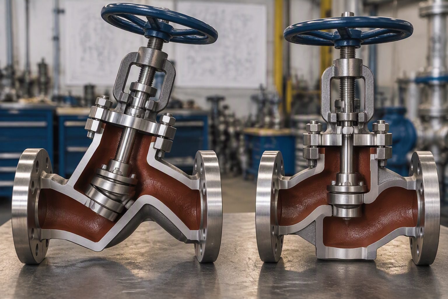
In my twenty years of designing critical process piping networks, selecting the correct valve trim remains one of the most consequential decisions for system reliability. When a disassembled diaphragm valve body sits on the workbench, the internal architecture immediately reveals its operational intent. The raised weir saddle shape visible inside the body contrasts sharply with the unobstructed flow path of straight-through alternatives, dictating everything from clean-in-place efficiency to erosive wear resistance.
Engineers must weigh hydraulic performance against sanitary requirements, balancing Cv values against dead-leg minimization. Understanding these fundamental geometric differences prevents catastrophic premature diaphragm failure, flow restriction, and contamination in high-purity or abrasive fluid services.
Key Engineering Takeaways
- Weir-style geometry optimizes sanitary cleanability and high-cycle bubble-tight shutoff in biopharmaceutical applications.
- Straight-through patterns accommodate high-viscosity slurries and fibrous media by eliminating internal flow obstructions.
- Elastomer and PTFE diaphragm selection must align with chemical compatibility, temperature limits, and fatigue endurance.
- Standard compliance with MSS SP-88 governs face-to-face dimensions and pressure-temperature ratings.
Diaphragm Valve Design Principles and Trim Mechanics
Mastering diaphragm valve design requires a thorough investigation of internal body contours. The internal geometry dictates fluid dynamics, pressure recovery, and particulate handling. When evaluating process requirements, engineers choose between the classic weir pattern and the full-bore straight-through pattern.
Each configuration imposes distinct hydrodynamic characteristics on the piping system, directly affecting pump head calculations, velocity profiles, and system energy losses.
Weir-Style Geometry and High-Purity Performance
The weir-style diaphragm valve features a raised central saddle cast directly into the valve body. This bridge provides an elevated seating surface against which the flexible diaphragm compresses to achieve shutoff.
The primary advantage of this raised weir is its self-draining capability when installed at the correct angular orientation in sanitary pipelines. Gravity assists fluid evacuation, preventing pooling and microbial growth in pharmaceutical water loops.
However, the weir restricts the flow cross-section. This constriction increases flow turbulence, lowers the flow coefficient (Cv), and creates higher pressure drops across the valve assembly compared to globe or gate valves.
Straight-Through Trim for Slurry and Viscous Media
In contrast, straight-through diaphragm valves eliminate the internal saddle. The body features a flat bottom contour aligned with the pipeline bore, allowing uninhibited media movement.
This unobstructed path makes straight-through valves ideal for mining slurries, crystal-laden chemical streams, and wastewater handling where suspended solids would otherwise accumulate on a weir.
Because the diaphragm must travel a greater vertical distance to close against the flat floor, straight-through designs utilize specialized reinforced elastomeric diaphragms capable of stretching significantly without structural degradation.
Critical Design Warning: High-Pressure Slurry Erosion
Operating straight-through valves in high-velocity slurry services (>3 m/s) induces severe localized turbulence directly beneath the descending compressor. Suspended abrasive particles impinging on the elastomeric diaphragm surface cause rapid erosion, core fiber exposure, and ultimate pressure boundary failure.
Engineers must verify that maximum pipeline flow velocities comply with ASTM erosion corrosion guidelines and select thick-walled rubber or polyurethane-backed diaphragms for abrasive slurry isolation.
Hydraulic Calculation and Pressure Drop Evaluation
Calculating pressure drop across a diaphragm valve requires utilizing standard hydrodynamic resistance coefficients (K factors) modified for flexible member deformation. The sizing equation follows standard industrial practices:
Delta P = (Q / Cv)^2 * (SG / N)
Where Q is volumetric flow rate, Cv is the valve flow coefficient at a given opening percentage, SG is specific gravity, and N is a unit conversion constant. Weir-style valves exhibit lower Cv values at intermediate openings, requiring larger nominal valve sizes in high-flow low-head systems.
Furthermore, bonnet assembly torque limits must be strictly calculated per ASME PCC-1 guidelines. Overtightening compressor bolts crushes the diaphragm bead, inducing cold flow and permanent elastomeric set, which destroys bubble-tight sealing integrity over thermal cycles.
Advantages & Disadvantages
Engineering Advantages
- Complete isolation of operating mechanism from corrosive or hazardous process media prevents stem packing leaks.
- Weir-style geometry provides exceptional bubble-tight shutoff even when handling entrained solid particles or suspended crystals.
- Streamlined internal cavities on high-purity weir models eliminate dead zones, supporting clean-in-place (CIP) and sterilization-in-place (SIP) protocols.
- Straight-through variants offer minimal flow resistance and accommodate high-viscosity fluids, sludges, and abrasive slurries without clogging.
- In-line diaphragm replacement reduces maintenance downtime without requiring complete valve body removal from the piping spool.
- Wide variety of elastomeric and fluoropolymer lining materials ensures superior chemical compatibility across aggressive acid and solvent services.
Engineering Disadvantages
- Weir-style valves create higher pressure drops and lower flow coefficients (Cv) due to internal flow constriction.
- Temperature and pressure operational windows are strictly constrained by elastomer and fluoropolymer mechanical degradation limits.
- Straight-through diaphragms undergo extreme mechanical flexing, resulting in shorter service life under high-frequency cycling.
- Large multi-turn handwheels or pneumatic actuators are required to overcome high closing forces against high line pressures.
- Diaphragm material permeability can lead to fugitive emissions or process contamination in ultra-pure gas services.
- Improper bolt torque during bonnet reassembly can cause elastomer extrusion, flange leakage, or premature diaphragm tearing.
Real-World Applications
Biopharmaceutical Water for Injection (WFI) Loops
Weir-style diaphragm valves serve as the industry standard for high-purity water and clean steam distribution loops. Their self-draining geometry and smooth electro-polished stainless steel bodies prevent microbial pooling, fully complying with ASME BPE standards for sterile processing equipment.
PTFE-faced EPDM diaphragms ensure complete chemical resistance during aggressive pure steam sterilization cycles exceeding 121 degrees Celsius.
Mining Slurry and Tailings Transport
Straight-through diaphragm valves excel in abrasive mineral slurry handling where abrasive iron ore or copper concentrates flow through carbon steel piping. The full-bore design eliminates turbulence pockets that cause localized pipe wall thinning and premature valve body washout.
Thick natural rubber linings absorb particle impact energy, extending maintenance intervals in harsh extraction plants.
Chlor-Alkali Chemical Manufacturing
Wet chlorine gas, hydrochloric acid, and caustic soda production require highly inert valve internals to prevent catastrophic body corrosion. Fluoropolymer-lined weir valves isolate metallic bonnets from corrosive vapors, ensuring absolute containment.
Bubble-tight shutoff prevents hazardous chemical migration into auxiliary instrument lines and secondary containment zones per OSHA safety mandates.
Municipal Wastewater Treatment Facilities
Raw sewage sludge, polymer dosing skids, and lime slurry injection lines utilize straight-through and weir diaphragm valves to handle fibrous suspended solids without binding. Traditional gate or ball valves trap debris in their cavities, preventing proper closure.
Diaphragm flexibility shears stringy materials across the weir surface, maintaining reliable flow control in continuous municipal operations.
Engineering Comparison of Diaphragm Valve Trim Geometries
When designing process systems handling aggressive chemicals, viscous fluids, or abrasive slurries, selecting the correct internal trim geometry dictates long-term asset reliability. In my two decades of reviewing piping specifications, I have observed that mismatched trim styles lead to accelerated elastomer degradation, premature leakage, and catastrophic product contamination.
The table below provides a rigorous comparative analysis between traditional weir-style diaphragm valves and straight-through (full-bore) designs, evaluating critical parameters including ASME B16.34 pressure ratings, flow coefficients, and cleanability metrics defined under 3-A Sanitary Standards.
| Performance Parameter | Weir-Style Diaphragm Valve | Straight-Through Trim Valve |
|---|---|---|
| Primary Flow Path | Raised center weir requiring fluid to flow upward over the bridge. | Unobstructed linear bore matching internal pipe diameter. |
| Flow Coefficient (Cv Range) | Lower Cv values due to flow restriction over the weir saddle. | Higher Cv values, minimizing pressure drop across the valve body. |
| Slurry & Solid Handling | Poor for heavy slurries; solids become trapped on the weir surface. | Excellent for abrasive slurries, viscid media, and suspended solids. |
| Cleanability (CIP/SIP) | Self-draining when mounted at precise angular inclinations. | Requires careful velocity profiling to eliminate dead zones. |
| Elastomer Stress Level | Lower travel distance; reduced flexural fatigue on the diaphragm. | High elongation stress as the membrane spans the full bore. |
| Applicable Industry Standards | BS 5156, MSS SP-88, ASME BPE | ASTM material specifications, MSS SP-88 |
Careful review of these technical parameters ensures your piping specification meets process hydraulic demands without compromising mechanical integrity or cleanability requirements.
Technical Mapping & Specifications Matrix
Modern process engineering requires strict traceability across all structural entities, acronyms, and governing design codes. When specifying automated or manual diaphragm assemblies for hazardous chemical processing plants, engineers must reconcile material compatibility charts with recognized international codes.
The matrix below systematically maps core structural entities, elastomeric compounds, and associated engineering standards, providing a definitive reference architecture for piping package integration.
| Entity / Acronym | Classification Type | Operational Parameters & Limits | Primary Code Reference |
|---|---|---|---|
| PTFE / TFM | Backed Diaphragm Material | Exceptional chemical resistance; temperature range up to 175 degrees C. | FDA CFR Title 21 |
| EPDM | Elastomer Membrane | Optimal for high-temperature steam sterilization (SIP) cycles up to 150 degrees C. | USP Class VI |
| MSS SP-88 | Design Standard | Diaphragm type industrial valves dimensional and pressure testing criteria. | MSS Standards |
| CIP / SIP | Sanitary Protocol | Clean-in-place chemical flush and steam-in-place sterilization regimes. | 3-A Sanitary |
| ASME BPE | Bioprocessing Standard | Surface finish roughness (Ra) requirements, typically below 0.5 micrometers. | ASME BPE |
Utilizing this structured matrix ensures that all engineering deliverables align seamlessly with regulatory compliance audits and material traceability mandates.
Valve Installation and Site Verification Checklist
Executing a flawless site installation requires rigorous adherence to pre-commissioning protocols. In my industrial piping audits, I frequently encounter premature diaphragm failures caused by improper torque sequences during body-to-bonnet bolting or incorrect angular mounting orientations that trap condensate and impede drainage.
The following verification framework establishes mandatory checkpoints for quality control engineers, piping supervisors, and mechanical contractors before hydro-testing and operational handoff.
Field Quality & Installation Verification Steps
-
1
Angular Mount Inspection: Verify that weir-style valves are installed with a 15-to-30-degree incline relative to the horizontal plane to guarantee complete drainability during clean-in-place cycles, complying with 3-A Sanitary Standards.
-
2
Fastener Torque Sequencing: Ensure all bonnet bolts are tightened in a criss-cross diagonal pattern using calibrated torque wrenches to distribute clamping stress uniformly across the elastomer flange without pinching.
-
3
Material Traceability Review: Cross-reference the heat number stamped on the cast valve body against certified material test reports (CMTRs) in accordance with ASME Section II.
-
4
Surface Roughness Verification: Inspect internal wetted surfaces using a portable profilometer to ensure finished Ra values meet or exceed specification requirements, specifically checking for pitting or casting inclusions.
-
5
Stroke and Travel Calibration: Perform full open-to-close actuator cycling tests to confirm that the compressor fully seats against the weir without excessive over-travel that risks tearing the elastomer membrane.
-
6
Hydrostatic Shell Testing: Conduct hydrostatic testing at 1.5 times the maximum allowable working pressure (MAWP) with the valve partially open, adhering strictly to ASME B16.34 guidelines.
Completing these verification milestones mitigates installation risks and ensures long-term operational compliance across demanding industrial environments.
Field Case Study: Solving Slurry Erosion in Chemical Processing
Real-world engineering challenges often test the limits of standard valve specifications. A recent project at a phosphoric acid production facility presented severe operational hurdles involving abrasive gypsum slurry handling, highlighting the critical importance of proper trim selection.
Engineering Problem: Premature Diaphragm Failure in Slurry Service
The plant experienced recurring, catastrophic failures of weir-style diaphragm valves installed in a 4-inch line transporting concentrated gypsum slurry containing suspended abrasive crystals at 80 degrees C.
- Abrasive slurry particles concentrated directly on the raised weir saddle during throttling operations, causing severe localized erosion of the elastomer.
- Turbulence and high fluid velocity over the weir accelerated abrasive wear, resulting in through-wall membrane punctures within three weeks of commissioning.
- Unplanned shutdowns resulted in significant production losses and high maintenance expenditures for emergency replacements.
- Standard EPDM diaphragms proved incompatible with the aggressive chemical and abrasive particulate combination.
Engineering Resolution: Transition to Straight-Through Trim & Specialized Elastomers
Following a comprehensive site audit and fluid dynamics review, the engineering team redesigned the piping node to replace the weir-style valves with straight-through full-bore trim architecture.
- Installed straight-through valves featuring high-grade natural rubber diaphragms optimized for abrasive slurry wear resistance.
- Eliminated the internal flow restriction and weir ledge, allowing smooth, unobstructed passage of suspended gypsum solids.
- Extended mean time between failures (MTBF) from 3 weeks to over 18 months of continuous, trouble-free operation.
- Achieved total compliance with ASME B16.34 pressure containment standards while drastically reducing maintenance downtime.
Engineering Recommendation: For any piping circuit involving suspended solids or abrasive slurries, always specify straight-through valve trim configurations paired with high-resilience elastomer compounds to prevent localized stagnation and premature wear.
Frequently Asked Engineering Questions
What is the primary operational difference between weir-type and straight-through diaphragm valves?
- Weir-style valves feature a raised central bridge that shortens the diaphragm travel distance and improves sealing integrity.
- Straight-through valves offer an unobstructed bore when fully open, making them ideal for high-viscosity fluids and solid-laden slurries.
- Selection must balance cleanability requirements against acceptable hydraulic head loss across the ASME piping network.
How do elastomer selection criteria impact chemical compatibility in process piping?
- PTFE backed with EPDM or elastomer offers superior chemical inertness for aggressive pharmaceutical acids and solvents.
- Neoprene and Nitrile provide excellent abrasion resistance for raw mineral slurries but fail under strong oxidizing agents.
- Engineers must evaluate temperature limits alongside chemical swelling data according to ASTM D1418 standards.
When should a straight-through valve be chosen over a weir-type design?
- Ideal for fibrous pulps, mining slurries, and highly viscous fluids that would settle on a weir crest.
- Allows pigging operations to pass straight through the piping loop without mechanical interference.
- Requires greater linear actuation force due to the stretching characteristics of the elongated elastomeric diaphragm.
What sanitary standards govern the design of biopharmaceutical diaphragm valves?
- Design must comply with ASME BPE standards for surface finish and cleanability.
- Body casting must be self-draining when mounted at the correct installation angle within the process skid.
- Diaphragm materials must pass USP Class VI biocompatibility tests and withstand repeated SIP steam sterilization cycles.
How does diaphragm fatigue affect preventive maintenance schedules?
- High cycling frequencies in throttling service shorten diaphragm life compared to pure on-off isolation duties.
- Thermal cycling from steam sterilization accelerates polymer aging and decreases tear strength.
- Maintenance teams should establish condition-based replacement intervals aligned with ISO 9001 reliability protocols.
Field Recommendation
- If you are designing a high-purity pharmaceutical water loop or sterile buffer line, specify weir-type diaphragm valves with electropolished 316L stainless steel bodies and PTFE-faced diaphragms to guarantee zero dead-leg entrapment and full ASME BPE compliance.
- If your process involves abrasive mineral slurries, heavy chemical waste streams, or viscous polymers with suspended solids, abandon weir geometries immediately and select straight-through bodies paired with high-durometer natural rubber or neoprene elastomers to prevent rapid localized erosion across the saddle.
- When sizing actuators for straight-through valves, always apply a minimum 30% safety factor over calculated breakaway thrust requirements, as the expansive stretching action of the long diaphragm under high line pressure demands significantly greater mechanical force than a traditional weir design.
- During initial piping layout design, ensure all weir-type valve bodies are oriented at an exact 15 to 30-degree incline relative to the horizontal plane to allow complete gravity draining during clean-in-place and steam-in-place validation cycles, eliminating pooling risks that cause microbial growth.
Complete Course on
Piping Engineering
Check Now
Key Features
- 125+ Hours Content
- 500+ Recorded Lectures
- 20+ Years Exp.
- Lifetime Access
Coverage
- Codes & Standards
- Layouts & Design
- Material Eng.
- Stress Analysis
