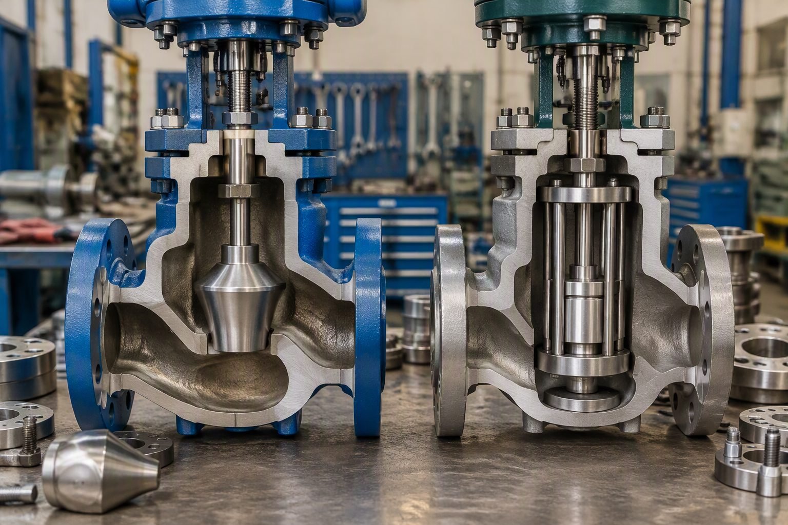
Control Valve Trim Types: Stem Guided vs. Cage Guided Stability Analysis
Over my two decades designing piping systems and high-pressure fluid networks, I have witnessed countless control valve failures traced directly to poor trim selection. When high-pressure-drop fluids flash or cavitate across a throttling element, the resulting lateral forces can easily destroy conventional stems.
Understanding the fundamental stability differences between stem-guided and cage-guided configurations is vital for instrumentation and piping engineers tasked with extending mean time between failures in harsh process plant environments.
Key Engineering Takeaways
- Stem-guided valves suit moderate pressure drops and clean fluids where low friction is paramount.
- Cage-guided trims provide robust lateral support, preventing plug side-play during severe throttling.
- Fluid velocity limits and cavitation parameters dictate the transition threshold between trim designs.
- Compliance with ASME structural limits ensures safe operation under maximum allowable working pressures.
Engineering Mechanics of Control Valve Trim Design
Stem-Guided Trim Architecture and Operating Limits
Stem-guided control valves rely on a relatively thin guided stem that positions the valve plug centrally within the seat ring. The guidance bushing is located remotely in the bonnet assembly, creating a long cantilever beam effect between the guide point and the seating surface.
When high-velocity fluid passes through the restricted opening, turbulent pressure fluctuations generate lateral thrust vectors across the plug surface. Because the support point is far away, these side forces induce bending moments along the stem.
In my design practice, I restrict stem-guided globe valves to applications where the pressure drop ratio factor (delta P over P1) remains below 0.3 for liquid service, or where steam velocities do not exceed 100 meters per second, thereby avoiding excessive stem deflection and packing wear.
Critical Design Warning: Stem Fatigue
Exceeding manufacturer velocity thresholds in stem-guided valves accelerates packing box degradation and can cause high-cycle fatigue failure at the stem-to-plug connection. Always cross-verify actuator thrust calculations with dynamic out-of-balance forces as outlined in ISA-75.19.01.
Cage-Guided Trim Architecture and High-Pressure Stability
Cage-guided control valves solve the cantilever vulnerability by enclosing the valve plug within a heavy-walled cylindrical sleeve, commonly known as the cage. The plug features a large cylindrical land that slides up and down directly against the inner bore of the cage.
This design provides continuous, rigid lateral guidance immediately adjacent to the point of pressure reduction. Even when handling severe pressure drops exceeding 70 bar, the close-fitting guide cage prevents lateral plug vibration and mechanical rattling.
Furthermore, the cage wall acts as an engineered fluid distribution system. By incorporating precision-drilled or milled windows, the cage divides the main flow into multiple jets, equalizing forces around the plug circumference and neutralizing side-load generation.
Fluid Velocity and Pressure Drop Calculations
Evaluating trim stability requires calculating the valve sizing coefficient and checking acoustic velocity limits. The flow capacity coefficient Cv is determined using standard sizing equations governed by IEC 60534-2-1:
Cv = Q * sqrt(SG / Delta P)
Where Q is volumetric flow rate, SG is specific gravity, and Delta P is pressure drop. When Delta P surges, fluid acceleration through the restricted trim area can induce choked flow, calculated via the pressure drop ratio factor FL:
Delta P_max = (FL^2) * (P1 – F_F * Pv)
Cage-guided trims excel in these high-energy regimes because their massive structural cross-section absorbs the severe reactive forces without transferring destructive harmonic frequencies up to the actuator stem.
Advantages & Disadvantages of Trim Types
Advantages
- Stem-Guided Simplicity: Low friction design allows rapid, highly responsive actuation for modulating loops.
- Stem-Guided Cost: Lower manufacturing and material costs for standard utility and low-pressure services.
- Cage-Guided Stability: Exceptional resistance to side loads and fluid-induced vibration during severe throttling.
- Cage-Guided Attenuation: Integrated flow windows allow multi-stage pressure reduction and noise mitigation.
- Maintenance Ease: Cage assemblies permit quick trim replacement without removing the valve body from the piping line.
Disadvantages
- Stem-Guided Vulnerability: Prone to stem bending and high-cycle fatigue under high-pressure-drop service.
- Stem-Guided Limits: Inadequate lateral support leads to premature packing leakage in severe throttling.
- Cage-Guided Friction: Larger sliding surface area increases breakout and running friction, demanding higher actuator thrust.
- Cage-Guided Sensitivity: Suspended solids or particulates can lodge between the cage bore and plug land, causing galling.
- Weight and Cost: Heavier overall valve assembly requiring robust pipe supports and higher capital expenditure.
Real-World Engineering Applications
High-Pressure Boiler Feedwater Regulation
Boiler feedwater pump recirculation and control stations experience massive pressure drops exceeding 150 bar. Cage-guided valves with multi-stage pressure-drop trims are mandatory here to prevent cavitation destruction and damp out destructive hydrodynamic vibrations.
Refinery Catalytic Cracking Unit Flue Gas
FCCU regenerator off-gas systems handle erosive catalyst fines at elevated temperatures. Stellite-hardened cage-guided trims maintain precise alignment and resist abrasive wear, ensuring reliable continuous operation between scheduled turnaround cycles.
Chemical Plant Utility Steam Distribution
General plant steam header pressure reduction stations operate with clean, dry media at moderate pressure drops. Stem-guided globe valves provide fast, responsive, and cost-effective control without the higher friction penalty of enclosed cage assemblies.
Natural Gas Pipeline Compressor Station Fuel Gas
Fuel gas skid supply regulators demand tight shutoff and stable low-flow throttling characteristics. Stem-guided single-seated trim configurations deliver ANSI Class IV or V shutoff reliability under steady, clean gas conditions.
LNG Liquefaction Cold Box Cryogenic Throttling
Extreme cryogenic temperatures down to minus 162 degrees Celsius cause material contraction and potential binding. Specially toleranced cage-guided assemblies with austenitic stainless steel bodies prevent thermal lockup and maintain structural integrity.
Control Valve Trim Performance Metrics
Selecting the appropriate valve trim configuration requires a rigorous evaluation of fluid dynamics, pressure drop profiles, and mechanical vibration limits defined under ASME standards. In my experience across high-capacity refinery units, misjudging velocity limits or lateral fluid forces inevitably leads to premature mechanical failure, accelerated seat wear, and catastrophic stem fatigue. The performance comparison below outlines the operational thresholds, velocity limits, and pressure drop boundaries for both stem guided and cage guided trim architectures.
Engineers must cross-reference these operational limits against ISA sizing equations and IEC hydrodynamic guidelines to prevent destructive cavitation and excessive dynamic instability during severe process upsets.
| Trim Architecture | Max Pressure Drop (bar) | Velocity Limit (m/s) | Vibration Resistance | Primary Code Standard |
|---|---|---|---|---|
| Stem Guided (Single Seated) | Up to 20 bar (Clean Liquid) | < 15 m/s (Liquid Service) | Low to Moderate | ASME B16.34 |
| Cage Guided (Balanced Plug) | Up to 150 bar (High Pressure) | < 40 m/s (With Anti-Cavitation) | Extremely High | ASME PTC 39.3 |
| Top and Bottom Guided | Up to 50 bar (Moderate Drop) | < 25 m/s (Two-Phase Flow) | Moderate to High | ISA-75.01.01 |
| Multi-Stage Cage Trim | > 200 bar (Severe Service) | < 30 m/s (Controlled Jet) | Maximum Stability | IEC 60534-8-4 |
Note: Values reflect standard industrial metallurgy (316SS with Stellite hardfacing) operating under continuous non-flashing liquid and gas duties.
Technical Mapping & Specifications Matrix
Advanced control valve engineering relies on precise semantic mapping of physical variables, structural acronyms, and governing industrial codes. When specifying high-pressure drop loops, instrumentation engineers must correlate actuator thrust requirements with trim reaction forces to prevent stem buckling and seat leakage. The entity matrix below establishes the core technical parameters, standard designations, and functional definitions utilized in modern piping and instrumentation design.
By standardizing these entities across engineering deliverables, project teams ensure seamless compliance with ASME and NACE material mandates for sour and high-pressure service.
| Entity Term | Standard Acronym | Governing Specification | Engineering Definition |
|---|---|---|---|
| Cage Guided Trim | CGT | ASME B16.34 | Plug fully enclosed in cylindrical drilled cage providing 360-degree lateral guidance. |
| Stem Guided Trim | SGT | ISA-75.03 | Plug guided exclusively by top stem bushing, vulnerable to high lateral fluid forces. |
| Pressure Recovery Factor | FL | IEC 60534-2-1 | Ratio determining choked flow limits and cavitation inception in control valves. |
| Valve Flow Coefficient | Cv / Kv | ISA-75.01.01 | Volumetric flow rate of water through fully open valve under specific pressure drop. |
Site Verification Checklist for Control Valve Trim Installation
Ensuring mechanical reliability and vibration resistance during field installation requires a structured quality assurance verification protocol. In my field commissioning work, skipping even a single pre-startup check on cage alignment or stem runout has resulted in catastrophic galling and premature trim failure within the first operational cycle.
Pre-Commissioning & Maintenance Inspection Checklist
- Stem Runout Measurement: Verify total indicated runout (TIR) on the valve stem is within manufacturer tolerances (ASME B16.34 mandates < 0.05 mm) to prevent bushing binding.
- Cage Clearance & Thermal Expansion: Inspect sliding clearances between the plug and cage bore, ensuring adequate thermal growth allowance for high-temperature steam service.
- Hardfacing Verification: Confirm Stellite or trim hardfacing thickness meets design specification sheets and is free from micro-cracking via dye penetrant testing (ASME Section V).
- Actuator Thrust Calibration: Match pneumatic or electric actuator bench set and spring stiffness against maximum shut-off pressure drop and unbalanced seating forces.
- Flange Bolt Torque Sequence: Apply cross-pattern torque to bonnet bolting in accordance with ASME PCC-1 guidelines to prevent body distortion and internal binding.
Every inspection point must be signed off by the lead piping engineer and instrumentation specialist before hydrotesting and hot commissioning. Adhering to these validation checkpoints guarantees compliance with international safety codes and extends mean time between failures across critical process units.
Field Case Study: Severe Service Trim Failure in Hydrocracker Let-Down Service
During commissioning of a high-pressure hydrocracker effluent let-down loop operating at 180 bar differential pressure, a stem-guided control valve experienced severe mechanical failure within 72 hours of initial startup.
The Problem: High Lateral Turbulence and Stem Fatigue
The stem-guided valve trim proved incapable of withstanding severe vortex shedding and high-velocity jet impact across the single seating surface.
- Lateral fluid forces deflected the unsupported lower plug past allowable elastic limits.
- Continuous vortex shedding induced high-frequency stem fatigue and premature packing failure.
- Severe localized cavitation eroded the seat ring within three days of continuous operation.
- The actuator lost precise positioning control due to excessive side-load friction in the top bushing.
The Outcome: Cage-Guided Redesign and Reliable Operation
Replacing the stem-guided trim with a balanced, multi-stage cage-guided assembly completely eliminated destructive vibration and restored stable process control.
- The 360-degree cylindrical cage provided rigid lateral support, absorbing all dynamic side loads.
- Multi-stage pressure profiling reduced fluid velocity below erosive thresholds (IEC 60534 limits).
- Maintenance cycles extended from 72 hours to over 4 years of continuous, uninterrupted refinery service.
- Seat leakage was successfully maintained within FCI 70-2 Class V standards.
Recommendation: For any liquid or gas service where pressure drop exceeds 20 bar or where fluid velocities surpass 15 meters per second, plant designers must bypass stem-guided valves and specify heavy-duty cage-guided trim architectures to ensure long-term mechanical integrity.
Frequently Asked Engineering Questions
What causes stem vibration in stem-guided control valves?
- Excessive pressure drop exceeding standard low-noise velocity limits.
- Unbalanced fluid forces acting on an asymmetrical plug contour.
- Loose bushing clearances leading to amplified mechanical resonance.
How does cage-guided trim control fluid velocity?
- Multi-stage pressure drop reduction across staggered port arrays.
- Symmetrical radial flow distribution neutralizing net lateral side-thrust.
- Complete mechanical enclosure preventing transverse plug deflection.
When should I specify cage-guided over stem-guided valves?
- Pressure drops exceeding 1,000 psi in liquid or gas applications.
- High flow capacity requirements demanding compact globe body profiles.
- Severe cavitation or flashing service requiring specialized attenuating cages.
What are the maintenance drawbacks of cage-guided trims?
- Cagewall galling caused by particulate entrapment in tight sliding clearances.
- Thermal binding at elevated operating temperatures requiring precise alloy pairing.
- Difficult cage extraction due to process scale and corrosion product buildup.
How do ASME standards govern valve trim leakage classes?
- Soft-seated cage designs achieving zero leakage for critical isolation.
- Lapped metal-to-metal seating maintained by precise cage-to-seat alignment.
- Thermal expansion allowances affecting tight shutoff integrity at high heat.
In my two decades of commissioning high-pressure hydrocarbon units, selecting the incorrect valve trim configuration consistently leads to premature mechanical failure and unplanned shutdowns. Based on field telemetry and valve autopsy reports, I advise applying the following rigorous engineering judgments for your next piping project:
- If your continuous operating pressure drop exceeds 25 percent of the inlet pressure or crosses 300 psi in liquid hydrocarbon service, specify cage-guided multi-stage trim immediately to eliminate the destructive fluid turbulence that destroys stem-guided bushings within months.
- When designing systems handling dirty or solids-laden catalyst slurry streams, reject tight-tolerance cage-guided trims in favor of rugged top-and-bottom stem-guided plugs with hardened stellite overlays to prevent catastrophic galling and jamming caused by particle entrapment.
- Always verify that the specified bonnet bolting material complies with ASME B16.34 stress limits when applying cage-guided valves in cyclic temperature services, ensuring differential thermal expansion between the heavy cage wall and body bore does not induce binding.
- Prioritize balanced cage-guided trim designs over conventional unbalanced stem-guided options on all globe valves larger than 4 inches operating above Class 300 ratings, as the massive reduction in actuator thrust requirements directly cuts capital cost and improves loop response speed.
Complete Course on
Piping Engineering
Check Now
Key Features
- 125+ Hours Content
- 500+ Recorded Lectures
- 20+ Years Exp.
- Lifetime Access
Coverage
- Codes & Standards
- Layouts & Design
- Material Eng.
- Stress Analysis
