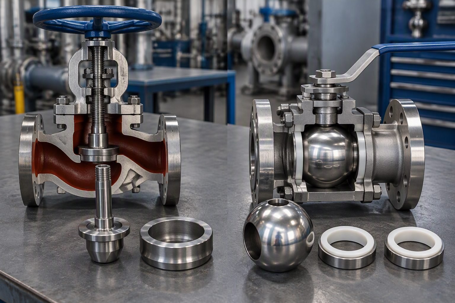
Control Valve Sizing Errors and Severe Trim Damage Prevention
In my two decades of reviewing distressed piping facilities, nothing destroys internal valve architecture faster than a poorly executed valve sizing calculation. When engineers select an oversized control valve to accommodate vague future expansions, the operational plug sits perilously close to the seat during normal flow rates. This high-velocity throttling zone triggers extreme localized pressure drops, vapor bubble implosion, and catastrophic metal pitting.
Understanding the fluid dynamics behind choked flow and valve trim degradation is essential for maintaining reliable process integrity. In this guide, I examine the mathematical foundations of sizing calculations, the mechanics of cavitation erosion, and engineering best practices to extend trim life under severe service conditions.
Key Engineering Takeaways
- Oversizing control valves shifts the operating characteristic, forcing high-velocity jet streams that erode plugs.
- Cavitation occurs when fluid pressure drops below vapor pressure and subsequently recovers, collapsing bubbles against metal surfaces.
- Accurate calculation of the valve flow coefficient (Cv) is mandatory per IEC 60534 standards.
- Selecting hardened trim materials like Stellite or tungsten carbide mitigates unavoidable high-pressure drop wear.
Control Valve Sizing Mechanics and Cavitation Physics
The fundamental sizing equation for liquid service relates the flow rate Q to the pressure drop Δ P across the valve trim using the flow coefficient Cv. In standard field applications, the sizing formula is expressed as Cv = Q √((G_f/Δ P)), where G_f represents the specific gravity of the fluid relative to water at standard conditions. When plant designers arbitrarily add safety factors of 50% to 100% to this calculated Cv, the resulting valve is grossly oversized for normal daily operations.
An oversized valve restricts flow through a tiny opening fraction, typically operating between 10% and 20% open during normal plant throughput. This condition forces the fluid through a severely restricted annular orifice, creating localized velocities that can easily exceed Mach 0.3 for liquids or sonic velocity for gases. The kinetic energy spike converts static pressure into dynamic velocity head, initiating the destructive sequence of cavitation.
The Mechanics of Cavitation and Vapor Collapse
Cavitation is a two-stage thermodynamic and hydrodynamic phenomenon that destroys valve internals. In the first stage, fluid accelerates through the vena contracta—the point of minimum cross-sectional area and maximum velocity downstream of the plug. According to Bernoulli’s principle, this velocity surge causes static pressure to plummet below the liquid’s vapor pressure (P_v). Microscopic vapor bubbles spontaneously nucleate within the fluid stream.
In the second stage, as the fluid expands into the larger downstream piping geometry, the flow decelerates and static pressure recovers. When local pressure exceeds vapor pressure again, the vapor bubbles instantly collapse or implode. This implosion generates microscopic high-velocity liquid micro-jets exceeding 1,000 meters per second, accompanied by localized shock wave pressures that can reach 1,000 megapascals. When these shock waves strike the metal surface of the valve plug or seat ring, they exceed the yield strength of standard austenitic stainless steels like 316L, tearing away metal flakes through fatigue and mechanical erosion.
Critical Design Warning: Choked Flow and Vaporization
If the pressure drop ratio (Δ P/P_1 – Pv) exceeds the valve recovery factor limit FL^2, the valve enters choked flow. Further increases in pressure drop will not yield higher flow rates, and vapor phase expansion will choke downstream piping, causing severe vibration, acoustic noise resembling gravel flowing through the pipe, and rapid mechanical degradation of internal trim components.
Advanced Sizing Parameters and Standard Compliance
To prevent sizing failures, engineers must incorporate piping geometry factors (F_p) and Reynolds number factors (F_r) into every sizing iteration, especially when dealing with high-viscosity fluids or reducing spools attached to valve bodies. The valve recovery coefficient (F_L) and pressure drop ratio factor (x_T) must be extracted directly from manufacturer certified flow test data complying with ANSI/ISA-75.02.01.
Furthermore, when operating conditions indicate incipient or advanced cavitation, standard single-stage trim must be replaced with specialized anti-cavitation trim. These designs utilize multi-stage pressure drop labyrinths, stacked disk sets, or perforated cage guides that break down the overall pressure drop into smaller, controlled increments. By stepping down the pressure gradually, the fluid static pressure is maintained safely above the vapor pressure threshold across all operating ranges, completely eliminating bubble collapse and preserving trim longevity.
Advantages of Precision Sizing & Anti-Cavitation Trim
- Eliminates destructive vapor bubble implosion, preventing deep pitting on plug seating surfaces.
- Extends valve operational lifecycle by 3x to 5x in severe pressure drop hydrocarbon services.
- Reduces plant acoustic noise levels by up to 15 dB(A) through controlled multi-stage velocity attenuation.
- Maintains precise loop controllability and rangeability by avoiding oversized low-lift deadbands.
- Protects downstream piping elbows and reducers from secondary impingement erosion-corrosion.
Disadvantages & Implementation Challenges
- Significantly higher initial procurement costs for engineered multi-stage labyrinth and stacked disk valve assemblies.
- Increased physical valve body weight and laying lengths requiring robust structural pipe supports.
- Higher susceptibility to particulate fouling and plugging when handling dirty or slurry-laden process fluids.
- Complex sizing software requirements needing exact thermodynamic fluid property inputs to avoid sizing errors.
- Longer manufacturing lead times for custom alloy trim components during emergency plant turnarounds.
High-Pressure Boiler Feedwater Regulating Valves
Boiler feedwater systems frequently experience high pressure drops as water is pumped from deaerators into high-pressure steam drums. When sizing errors cause undersized or poorly matched control valves in these power plant loops, flashing and thermal shock rapidly erode trim guides, resulting in feedwater bypass and boiler trip events. Implementing multi-stage cage-guided trims ensures stable, erosion-free regulation under extreme thermal gradients.
Refinery Hydroprocessing Reactor Effluent Letdown
Hydrocracker and desulfurization high-pressure separator level control valves handle severe multi-phase hydrocarbon streams laden with dissolved sour gases. Sizing mistakes that ignore gas breakout and mixture density shifts lead to intense cavitation and aggressive hydrogen-induced cracking or localized trim destruction. Precise sizing per API 553 guidelines is mandatory to ensure continuous refinery operation.
LNG Liquefaction Mixed Refrigerant Expansion Loops
Cryogenic liquefaction processes utilize Joule-Thomson expansion valves operating at extreme sub-zero temperatures with high pressure drops. Undiagnosed two-phase flashing in these cryogenic mixed refrigerant loops creates immense mechanical stress and vibration. Engineers must utilize specialized low-temperature alloy trims with precise opening characteristic curves to withstand thermal contraction and erosive fluid phase changes.
Chemical Plant Acidic Slurry Pressure Control
In chemical synthesis units, control valves handling corrosive mineral acid slurries combine chemical attack with mechanical cavitation wear. Sizing errors that result in excessive fluid velocities accelerate localized protective passive film stripping on alloy surfaces. Applying tungsten carbide trim materials combined with correct sizing coefficients prevents premature wall thinning and toxic chemical containment loss.
Desalination High-Pressure Reverse Osmosis Reject Streams
Reverse osmosis energy recovery and brine reject control valves manage concentrated high-salinity seawater streams under high pressure differentials. Cavitation and impingement erosion in these aggressive saline environments can destroy standard 316 stainless steel trim within weeks. Accurate sizing paired with super duplex stainless steel or ceramic trim assemblies is essential for sustained plant reliability.
Valve Sizing Parameters and Cavitation Index Thresholds
Accurate hydraulic sizing requires rigorous evaluation of pressure drop ratios, valve flow coefficients, and fluid vapor pressures. When sizing control valves for liquid service, engineers must cross-reference actual operating conditions against manufacturer-supplied data sheets and industry standards such as ANSI/ISA-75.01.01.
The engineering data table below details critical sizing parameters, acceptable operating limits, and associated trim failure mechanisms when thresholds are violated. These values govern fluid acceleration and flash point boundaries across high-pressure drop liquid systems.
| Parameter Name | Symbol / Unit | Design Limit | Failure Mode on Violation |
|---|---|---|---|
| Valve Flow Coefficient | Cv (gpm/sqrt(psi)) | 30% to 80% open | Oversizing causes wire-drawing and accelerated plug erosion. |
| Incipient Cavitation Index | kc (dimensionless) | Greater than 0.25 | Severe localized pitting on downstream plug and seat faces. |
| Choked Flow Pressure Ratio | FL (dimensionless) | 0.50 to 0.90 typical | Vena contracta pressure drops below vapor pressure, causing flash. |
| Maximum Velocity Limit | V (m/s or ft/s) | Under 15 m/s liquids | Erosion-corrosion and mechanical vibration fatigue. |
| Acoustic Sound Pressure | SPL (dBA) | Less than 85 dBA | High-frequency noise leading to piping weld degradation. |
Note: Operating continuously outside these established hydraulic design limits violates ASME B16.34 structural integrity guidelines and accelerates maintenance turnaround intervals.
Technical Mapping & Specifications Matrix
Modern industrial process plants rely on standardized terminology, rigorous fluid dynamic equations, and verified material specifications to prevent catastrophic valve trim failure. When evaluating complex control valve assemblies, piping engineers must align physical operating envelopes with recognized global engineering standards and material codes.
The matrix outlined below maps critical engineering entities, structural acronyms, physical parameters, and their governing industry standards. This reference structure ensures cross-functional alignment between instrumentation, mechanical, and piping design teams during front-end engineering design phases.
| Entity / Term | Category | Physical Parameter & Scope | Governing Standard |
|---|---|---|---|
| Control Valve Sizing | Hydraulic Design | Determines required Cv and trim geometry based on mass flow rates. | ANSI/ISA-75.01.01 |
| Cavitation Index | Fluid Dynamics | Measures proximity to vapor pressure drop at the valve vena contracta. | IEC 60534-2-3 |
| Stellite Hardfacing | Metallurgy | Cobalt-base alloy overlay applied to plug and seat to resist pitting. | ASME Section IX |
| Valve Face-to-Face | Dimensional | Standardized laying lengths for flanged and welded valve bodies. | ASME B16.10 |
| Hydrostatic Testing | Quality Assurance | Shell and seat leakage verification under 1.5x design pressure. | API 598 |
Adhering to these mapping parameters during specification reviews prevents costly field rework, premature maintenance turnarounds, and catastrophic containment failures.
Site Verification Checklist for Control Valve Sizing
Control valve sizing verification requires a systematic multi-step site assessment before final equipment commissioning or after severe maintenance overhauls. Piping and instrumentation engineers must validate that process fluid properties, pressure differentials, and piping geometry match design specifications to prevent destructive cavitation and premature trim degradation.
Execute the following detailed verification protocol on-site to ensure compliance with ANSI/ISA-75.01.01 and ASME B16.34 standards.
Control Valve Sizing and Anti-Cavitation Audit Steps
-
Verify Maximum and Minimum Flow Rates: Confirm that process data sheets reflect actual operating flow conditions rather than excessive safety margins that lead to valve oversizing and low-lift wire-drawing.
-
Calculate Operating Pressure Drop Ratio: Evaluate upstream and downstream pressure gauges across the valve body to ensure the actual pressure drop does not exceed the critical pressure drop ratio for the specific trim type.
-
Check Fluid Vapor Pressure Margins: Review liquid temperature and vapor pressure data to confirm that pressure at the vena contracta remains safely above fluid vapor pressure, eliminating incipient cavitation.
-
Inspect Valve Trim Material Hardness: Ensure plug and seat surfaces are equipped with Stellite hardfacing or tungsten carbide coatings when handling high-differential pressure liquid or slurry services.
-
Evaluate Upstream and Downstream Pipe Diameters: Verify that reducer and expander fittings adjacent to the control valve do not induce flow turbulence or unpredicted pressure recovery variations.
-
Acoustic and Vibration Baseline Testing: Perform field sound level measurements across the valve body to verify that high-frequency noise emissions remain below regulatory threshold limits.
Document all verification findings in the permanent plant equipment history file. Immediate corrective action must be scheduled if any parameter exceeds allowable operating limits.
Field Case Study: Real-World Application
A major hydrocarbon processing facility experienced severe process upsets and high-frequency acoustic noise on a high-pressure boiler feedwater letdown control valve. The 6-inch globe valve exhibited catastrophic trim degradation within six months of initial commissioning, threatening plant steam generation reliability.
Problem Analysis:
Investigation revealed that extreme valve oversizing combined with unmitigated pressure drops triggered violent cavitation and deep metal pitting on internal trim surfaces.
- The original valve was selected with a oversized Cv of 280, operating continuously below 15% valve opening during normal plant turndown conditions.
- Pressure drop across the valve exceeded 3.5 MPa, causing the vena contracta pressure to drop far below the feedwater vapor pressure.
- Vapor bubbles collapsed violently against the 316 stainless steel plug and seat, creating localized micro-jets exceeding 1,000 meters per second.
- Deep grooves and pitted craters formed on the seating surface, resulting in severe internal bypass leakage and loss of precise level control.
- Acoustic monitoring recorded noise levels exceeding 105 dBA, causing structural vibration fatigue on adjacent piping support welds.
To resolve this severe failure, our engineering team performed a complete hydraulic recalculation and redesigned the valve station according to ANSI/ISA-75.01.01 standards.
Engineering Resolution & Outcome:
Replacing the oversized single-stage valve with a correctly sized multi-stage anti-cavitation trim assembly completely eliminated destructive bubble collapse and restored stable hydraulic control.
- Installed a 4-inch globe valve with a multi-stage labyrinth disk trim stack, shifting the pressure drop across successive pressure-reduction steps.
- Upgraded internal trim material to hardened stainless steel with Stellite hardfacing on all seating and guidance surfaces.
- Reduced operating noise levels from 105 dBA down to 78 dBA, well within Occupational Safety and Health Administration limits.
- Eliminated internal bypass leakage entirely, extending scheduled maintenance turnaround intervals from 6 months to over 5 years.
- Saved the facility over 250,000 in recurring emergency replacement and unbudgeted production downtime costs.
Recommendation: Always perform rigorous multi-scenario sizing calculations and evaluate anti-cavitation trim options during the initial FEED stage for any liquid service valve experiencing high pressure drop ratios.
Frequently Asked Engineering Questions
How does control valve oversizing directly cause cavitation?
- High pressure drop occurs across an extremely narrow throttling gap.
- Local velocity increases drastically, dropping static pressure below the fluid’s vapor pressure.
- Subsequent pressure recovery collapses vapor bubbles, causing severe trim erosion.
What standards govern the calculation of control valve sizing and cavitation?
- ISA-75.01.01 defines the mathematical formulas for flow capacity.
- IEC 60534-2-1 standardizes industrial-process control valve sizing equations.
- ISA-RP75.23 provides specific guidelines for assessing cavitation damage potential.
How do you distinguish between cavitation damage and flashing damage?
- Cavitation exhibits localized, clean, shiny pitting due to micro-jet bubble collapses.
- Flashing presents a smooth, polished, sandblasted appearance because downstream pressure remains below vapor pressure.
- Cavitation occurs when downstream pressure recovers above vapor pressure, whereas flashing does not recover.
What is the role of the liquid pressure recovery factor (FL) in valve sizing?
- Low FL values indicate high-recovery valves (like ball or butterfly valves) prone to cavitation.
- High FL values indicate low-recovery valves (like globe valves) that resist cavitation better.
- Using an incorrect FL during calculations leads to inaccurate sizing and premature trim failure.
What trim modifications can mitigate cavitation in existing control valves?
- Multi-stage trim splits the total pressure drop into smaller, non-cavitating steps.
- Drilled-hole cages divide the flow into small, opposing jets to dissipate energy.
- Hardened materials like Stellite extend the operating life of the plug and seat.
Why is the valve operating range (turndown) critical for sizing?
- Operating below 10% lift causes high-velocity wire-drawing and rapid seat erosion.
- Selecting a valve with an equal percentage characteristic helps maintain control at low flows.
- Proper turndown analysis ensures the valve operates within its stable, non-damaging control window.
Field Recommendation
Based on my 20+ years of piping engineering experience, resolving severe trim damage requires moving beyond standard sizing spreadsheets and making decisive, application-specific engineering choices:
- If your process exhibits a turndown ratio exceeding 10:1 with high differential pressures, I recommend installing a split-range two-valve configuration rather than a single oversized globe valve. This prevents the primary valve from operating below 10% lift where high-velocity wire-drawing destroys the seat.
- When retrofitting a system experiencing severe cavitation pitting, select a multi-stage path trim with Stellite-faced seating surfaces instead of standard single-stage linear trim. In my experience, the multi-stage design forces incremental pressure drops that keep the fluid pressure safely above its vapor pressure.
- If your sizing calculations yield a calculated Cv that falls within the lower 15% of the valve’s maximum capacity, select a reduced-trim option within a smaller valve body. This maintains high control resolution and keeps the plug further away from the seat during normal throttling operations.
Complete Course on
Piping Engineering
Check Now
Key Features
- 125+ Hours Content
- 500+ Recorded Lectures
- 20+ Years Exp.
- Lifetime Access
Coverage
- Codes & Standards
- Layouts & Design
- Material Eng.
- Stress Analysis
