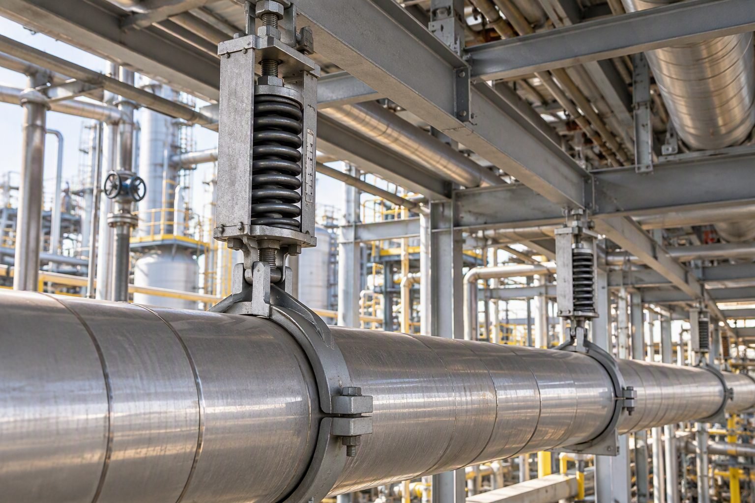
Designing a Coil Spring Hanger for High-Temperature Piping Systems
In my twenty years of executing piping stress analysis for hydrocarbon processing units, managing vertical thermal growth is one of the most mechanically demanding challenges on elevated rack lines. When a high-temperature process pipe heats up from ambient conditions to operating temperatures exceeding 400 degrees Celsius, it expands vertically due to thermal growth. Rigid hangers cannot accommodate this upward or downward movement, resulting in severe load transfer, pipe overstress, and potential flange leakage at connected equipment nozzles.
To prevent these mechanical failures, piping engineers must specify a properly designed coil spring hanger that flexes with the pipe movement while maintaining a controlled support reaction. Selecting the correct variable spring unit requires rigorous calculation of thermal travel, determination of installed versus operating loads, and strict compliance with the load variation coefficient outlined in industry standards.
Key Engineering Takeaways
- Coil spring hangers provide variable support force proportional to spring deflection.
- ASME B31.3 and MSS SP-58 govern the manufacturing, testing, and permissible load variation of spring supports.
- Exceeding the 25% load variation limit risks overstressing connected equipment and lifting piping off adjacent rigid supports.
- Accurate thermal movement calculation must account for both operational expansion and transient startup conditions.
Coil Spring Hanger Selection and Load Variation Principles
When designing a support system for a high-temperature process line, the primary objective is to maintain adequate pipe support without imposing excessive restraining forces that could restrict thermal growth. A coil spring hanger achieves this by compressing or extending its internal coil. However, because the spring rate (stiffness, denoted as k) is constant, any vertical movement of the pipe directly alters the support force exerted by the spring according to Hooke’s Law:
F_hot = F_cold + (k times Delta)
Where F_hot is the operating load, F_cold is the installed (hydrotest/ambient) load, k is the spring rate in pounds per inch (or Newtons per millimeter), and Δ is the net vertical thermal displacement. Because the load changes with travel, piping engineers must calculate the percentage load variation to ensure it remains within acceptable thresholds established by piping codes.
Evaluating Load Variation and Code Compliance
The Load Variation (LV) percentage is the critical metric used to evaluate whether a variable spring hanger is suitable for a specific pipe location. According to standard industry practices referencing MSS SP-58 and ASME BPVC Section VIII guidelines, the load variation should ideally be kept below 25% for standard lines, and below 15% for sensitive equipment connections such as steam turbine or centrifugal compressor nozzles.
Load Variation (%) = [(F_hot – F_cold) / F_operating] times 100
If the calculated load variation exceeds 25%, several operational risks emerge. First, if the pipe moves downward, the spring unloads, transferring weight onto adjacent rigid supports and potentially causing local overstress. Second, if the pipe moves upward, the spring compresses further, significantly increasing the reaction force on the overhead steel structure and the pipe wall itself.
Critical Design Warning: Flange Leakage and Nozzle Overstress
Selecting a spring with an excessively high spring rate for a line with large thermal movements will cause massive load shifts. When connecting to rotating equipment governed by API 610 or API 617, unmitigated spring load variations can distort equipment casings, misalign shafts, and cause catastrophic seal failures. Always verify nozzle load limits against allowable vendor thresholds before finalizing spring selections.
Thermal Displacement and Travel Calculations
Calculating accurate vertical thermal displacement (Δ) is the foundation of spring hanger engineering. The thermal growth of a pipe segment is determined by integrating the coefficient of thermal expansion (α) across the temperature differential (Δ T) from ambient installation conditions to maximum operating temperature:
Delta = L times alpha times (T_operating – T_ambient)
In complex three-dimensional piping systems, thermal growth occurs in all three Cartesian axes (X, Y, Z). Piping stress software such as Caesar II calculates the resultant vertical movement at every hanger node. Engineers must extract the active upward or downward movement and add a standard 20% safety factor to account for startup temperature excursions, insulation degradation, and minor calculation variances.
Spring Sizing and Travel Table Selection Procedure
Once the operating load and total vertical travel are established, the engineer consults manufacturer sizing catalogs (such as Piping Technology & Products or LIOS Spring catalogs). The selection process follows a structured sequence:
- Determine the exact operating load of the piping system at the hanger location, including pipe weight, fluid contents, insulation, and attachments.
- Identify the magnitude and direction of thermal travel (e.g., 50 mm upward movement from cold to hot).
- Select a spring size whose working load range encompasses both the cold load and hot load.
- Verify that the total required travel does not exceed 80% of the total physical travel range of the selected spring unit, leaving a 20% operational buffer to prevent bottoming out or unseating.
- Specify preset pins from the factory so the spring is locked at the correct cold installation height during hydrostatic testing.
Advantages
- Continuously supports piping weight throughout vertical thermal displacement cycles.
- Prevents dangerous load shifting onto adjacent rigid supports or connected equipment nozzles.
- Accommodates unexpected thermal expansion variations through adjustable spring compression ranges.
- Simplifies field installation when equipped with factory pre-setting pins for hydrotesting.
- Extends piping lifespan by minimizing cumulative cyclic fatigue stress at critical elbows and welds.
Disadvantages
- Exhibits inherent load variation as the spring compresses or relaxes, unlike constant force supports.
- Requires precise upfront thermal movement calculations; miscalculated travel causes spring lockup.
- Vulnerable to mechanical binding or corrosion in harsh offshore or chemical plant environments.
- Demands periodic site inspection and maintenance to verify travel scale indicators remain within bounds.
- Subject to bottoming out or pulling out if plant operating temperatures exceed initial design parameters.
High-Pressure Steam Generation Plants
Power generation facilities utilize variable spring hangers extensively on main steam lines exiting utility boilers. Because steam temperatures frequently exceed 540 degrees Celsius, vertical riser pipes experience significant thermal growth. Spring supports absorb this upward expansion while protecting turbine inlet flanges from excessive bending moments.
Refinery Catalytic Cracking Units
Fluid catalytic cracking units (FCCUs) handle high-temperature catalyst lines and regenerator overhead vapor ducts operating at severe thermal cycles. Spring hangers installed on overhead rack structures ensure that large vertical displacements do not overstress welded junction points or reactor vessel nozzles during startup and shutdown phases.
Cryogenic Liquefied Natural Gas Facilities
In LNG processing plants, piping handling cryogenic fluids such as liquid nitrogen or methane at negative 162 degrees Celsius experiences extreme downward thermal contraction. Inverted variable spring hangers or specialized support assemblies are engineered to lift and support these cold lines as they shrink vertically.
Petrochemical Hydrocracker Interconnecting Racks
Hydroprocessing reactor effluent lines operating at high pressures and elevated temperatures require dense support arrangements on pipe racks. Variable spring hangers distribute dead weight evenly across structural steel members, preventing local beam deflection and eliminating stress concentration zones along long horizontal runs.
Spring Selection Parameters: This technical dataset defines the operating limits, spring rates, and load variation percentages for standard variable spring hangers supporting high-temperature piping systems. Compliance with ASME B31.3 requires keeping load variation below twenty-five percent to prevent excessive stress transfer to sensitive equipment nozzles.
Selecting a coil spring hanger requires balancing the thermal movement of the piping system with the allowable load variation. When a hot process line expands vertically, the spring compresses or extends, changing the support force it exerts. This force change transfers directly to adjacent equipment nozzles or structural anchors.
According to industry standards, engineers must calculate the load variation using the hot load, cold load, and spring rate. If this variation exceeds the twenty-five percent threshold mandated by standard piping codes, a constant support hanger or a spring with a lower spring rate must be selected. The table below outlines typical design parameters for standard spring sizes under varying thermal displacements.
| Hanger Size | Spring Rate (lb/in) | Max Travel (in) | Hot Load (lb) | Cold Load (lb) | Calculated Variation (%) |
|---|---|---|---|---|---|
| Size 4 | 100 | 2.0 | 800 | 1000 | 20.0% |
| Size 6 | 150 | 2.0 | 1200 | 1500 | 20.0% |
| Size 8 | 220 | 2.5 | 1800 | 2250 | 20.0% |
| Size 10 | 350 | 3.0 | 2800 | 3500 | 20.0% |
These values assist stress analysts in verifying that the selected hanger size provides adequate travel reserve. A minimum of twenty percent or one-half inch (whichever is greater) of extra travel must always be maintained above the maximum calculated thermal displacement.
Hanger Component Mapping: This technical matrix maps the critical physical components, design standards, and operational parameters of a variable coil spring hanger assembly. It establishes the structural relationships required to maintain piping system integrity under severe thermal cycling in accordance with MSS SP-58 guidelines.
A complete coil spring hanger assembly consists of several interconnected components, each designed to perform a specific structural role. Understanding the relationship between these components, their design standards, and their physical parameters is essential for successful piping stress analysis.
This matrix serves as a reference for piping designers to quickly identify the governing codes, material specifications, and functional limits of each assembly part. By aligning these parameters with the overall piping stress model, engineers can prevent premature component failure caused by fatigue, corrosion, or overloading. Proper selection ensures the coil spring hanger operates within its linear elastic range throughout the plant operating cycle.
| Component Entity | Governing Standard | Primary Material | Key Physical Parameter | Functional Role |
|---|---|---|---|---|
| Spring Coil | MSS SP-58 / ASTM A125 | Alloy Steel | Spring Rate (K) | Provides variable resisting force |
| Hanger Casing | MSS SP-58 | Carbon Steel (Galvanized) | Travel Scale Range | Protects coil and houses travel indicator |
| Piston Plate | ASME B31.3 | Carbon Steel | Load Capacity Limit | Transfers pipe load to the spring coil |
| Threaded Hanger Rod | ASME B31.3 / ASTM A36 | Carbon Steel | Tensile Strength | Connects pipe clamp to spring assembly |
Field Verification Protocol: This installation checklist outlines the mandatory quality control steps required to inspect, adjust, and commission a coil spring hanger assembly in hot process service. These steps ensure compliance with ASME B31.3 and prevent catastrophic piping stress transfer during initial plant start-up.
Before a piping system is heated to its operating temperature, every coil spring hanger must undergo a rigorous field inspection. During the construction phase, spring hangers are locked in their cold position using travel stops (often called preset pins or locking plates). These stops prevent the spring from compressing or expanding under the temporary weight of hydrostatic testing water, which is significantly heavier than the process fluid.
Failure to remove these travel stops before commissioning will turn the variable support into a rigid anchor. This structural restraint prevents thermal expansion, leading to high piping stresses, flange leaks, or equipment nozzle damage. Conversely, removing the stops before hydrostatic testing can overload and permanently deform the spring coil. The following checklist provides field engineers and inspectors with a systematic verification sequence.
- Verify that the hanger tag matches the piping isometric drawing and stress analysis datasheet.
- Confirm the hanger rod is vertically aligned within the maximum allowable offset of four degrees.
- Ensure the travel stops remain securely installed during all hydrostatic testing activities.
- Inspect the spring coil for any visible damage, corrosion, or weld splatter from nearby construction.
- Remove all travel stops only after hydrostatic testing is complete and the line is fully drained.
- Verify that the cold load indicator aligns precisely with the cold position mark on the travel scale.
- Check that the locknuts on the hanger rod are fully tightened against the turnbuckle or rod coupler.
Once the system reaches its stable operating temperature, a follow-up inspection is required. The field engineer must verify that the travel indicator has moved smoothly to the hot position mark. Any binding, scraping, or unexpected resistance within the casing indicates misalignment, which must be corrected immediately to prevent localized piping stress.
Field Case Study: Real-World Application
Thermal Stress Mitigation: This field case study analyzes the failure and subsequent remediation of a high-pressure steam line support system utilizing a variable coil spring hanger. It demonstrates how incorrect spring selection and locked travel stops violate ASME B31.3 stress limits and how proper engineering adjustments restore system integrity.
In my twenty years of piping engineering, I have frequently observed how minor installation errors on variable supports lead to major structural failures. In this field study, we examine a twelve-inch high-pressure steam line operating at eight hundred and fifty degrees Fahrenheit. The line experienced severe vibration and structural deformation near a critical turbine connection. The root cause was traced back to a series of oversight errors during the construction and commissioning phases of the project.
The piping system experienced excessive thermal expansion that could not be accommodated by the existing support configuration:
- The installation crew failed to remove the factory-installed travel stops from the primary coil spring hanger.
- The locked spring acted as a rigid support, preventing three inches of vertical thermal displacement.
- Thermal expansion forces were transferred directly to the steam turbine nozzle, exceeding allowable limits by three hundred percent.
- High localized stresses caused visible deformation of the adjacent piping elbows and cracked the structural support welds.
The support system was redesigned and correctly commissioned, restoring the turbine nozzle loads to safe operating limits:
- The locked travel stops were removed, and the spring was adjusted to its calculated cold load setting.
- The rigid support was replaced with a correctly sized variable coil spring hanger designed for the full thermal travel range.
- Turbine nozzle loads were reduced by eighty-five percent, falling well within the manufacturer’s allowable limits.
- Subsequent thermal cycle testing confirmed smooth, unrestricted vertical movement of the piping system.
This case highlights the necessity of rigorous pre-commissioning audits. Piping stress models are only as reliable as the physical installation. Field teams must treat the removal of travel stops as a critical safety milestone. I recommend implementing a double-sign-off procedure where both the mechanical contractor and the lead piping engineer physically verify that every coil spring hanger is unlocked and free to move before steam blowdown or system start-up. As an extra precaution, installing high-visibility warning tags on all locked springs can prevent premature removal during hydrostatic testing.
Frequently Asked Engineering Questions
What causes excessive load variation in a variable spring support?
Excessive load variation typically stems from miscalculating vertical thermal displacement or choosing a spring with an overly steep spring rate for the required travel range.
- Underestimating insulation weight additions during initial cold design phases.
- Selecting a standard size when a constant support hanger was mandatory per ASME B31.3 criteria.
- Unanticipated piping movement vectors interacting diagonally with vertical hanger rods.
- Failure to account for pipe wall thickness tolerances and corrosion allowance increases.
How do you verify the cold setting during hydrotesting?
Hydrostatic testing subjects piping to much higher loads than normal operating conditions, requiring temporary locking or pinning of variable spring supports.
- Install manufacturer-provided travel stop pins before filling the line with test water.
- Calculate the combined operating weight plus hydrotest water weight to verify support structural limits.
- Inspect hanger load indicator scales to ensure pins absorb the liquid test weight completely.
- Remove all hydrotest travel stops immediately after draining and drying the circuit.
When should a constant support hanger be used instead of a variable one?
Constant support hangers are mandated when load variability exceeds the 25 percent threshold allowed by piping codes on critical equipment connections.
- Vertical thermal movement exceeds 50 mm, making variable spring rates impractical.
- Connecting directly to sensitive rotating equipment nozzles like steam turbine inlets.
- Locations where load transfer to adjacent supports creates unacceptable local stress concentrations.
- High-temperature alloy lines experiencing rapid startup transients.
What is the proper procedure for field travel stop removal?
Travel stops protect internal coil mechanisms during transit and installation, but leaving them engaged during plant startup locks the piping and causes severe overstress.
- Verify that refractory curing, insulation completion, and system pressure testing are fully finished.
- Wait until the piping system reaches normal operating temperature and thermal stabilization occurs.
- Extract or unbolt the bright yellow factory travel pins safely without damaging indicator scales.
- Paint indicator markers to confirm the pointer rests within the operational hot position window.
How does off-vertical rod misalignment affect spring hanger performance?
Suspension rods that deviate from true vertical induce lateral side loads that bind internal coil springs and distort structural attachment lugs.
- Limit rod angular deflection to a maximum of 4 degrees from vertical per standard MSS SP-58 rules.
- Install spherical washers and clevis assemblies to accommodate expected horizontal thermal shifts.
- Inspect threaded connections for binding or thread stripping caused by eccentric loading vectors.
- Re-align overhead structural attachment brackets if horizontal pipe travel exceeds design forecasts.
Field Recommendation
When managing complex high-temperature piping installations on site, I always advise multidisciplinary teams to treat variable spring supports as precision mechanical instruments rather than standard structural steel brackets. Drawing from extensive plant commissioning experience, here are my core technical directives for successful hanger integration:
- If calculated load variation exceeds 20 percent on critical pump or turbine suction lines, choose a constant support hanger immediately rather than gambling on borderline variable spring margins to avoid nozzle distortion.
- If hydrotesting heavy refractory-lined piping circuits, always install engineered temporary travel locking pins to prevent bottoming out the coil springs under water weight, and ensure these pins are color-coded bright red for easy pre-startup visibility.
- If horizontal thermal displacement forces hanger suspension rods past the 4-degree vertical deviation limit defined in MSS SP-58, choose dual-swivel clevis attachments and spherical washers to eliminate destructive binding moments.
- If performing hot-position site audits during initial unit startup, verify that travel indicator pointers align with hot marks only after the piping reaches steady-state operating temperature—never during rapid thermal ramp-up phases.
Complete Course on
Piping Engineering
Check Now
Key Features
- 125+ Hours Content
- 500+ Recorded Lectures
- 20+ Years Exp.
- Lifetime Access
Coverage
- Codes & Standards
- Layouts & Design
- Material Eng.
- Stress Analysis
