Choke Valve Trim Materials: Tungsten Carbide vs Stellite Hardfacing
Choke valve trim materials selection governs high-pressure choke assembly longevity in abrasive and erosive oilfield environments, ensuring strict compliance with API 6A and ASME B16.34 design specifications.
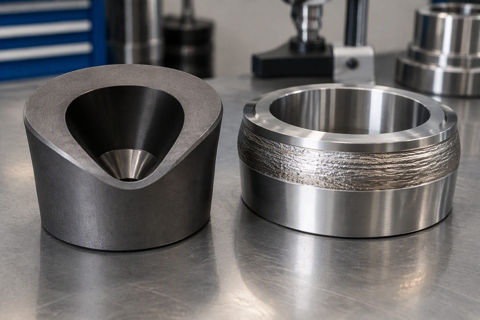
When I inspect high-pressure wellhead choke components on the workshop floor, the stark visual contrast between a dark matte tungsten carbide choke bean insert and a bright silver Stellite weld overlay band tells an immediate engineering story. Selecting between these two metallurgy paradigms defines whether a choke trim survives aggressive sand-laden production fluids or fails prematurely due to severe cavitation and solid particle erosion. In my two decades managing critical subsea and surface piping packages, improper trim material pairing remains a primary driver of catastrophic seat leakage and pressure boundary degradation.
Surface choke valves operate under punishing differential pressure drops, transforming potential energy into high-velocity fluid jets that relentlessly hammer internal trim boundaries. Balancing extreme hardness for erosion mitigation against adequate fracture toughness and galling resistance requires rigorous metallurgical scrutiny. This technical guide explores the mechanical behaviors, microstructural properties, and industrial standards governing these two elite valve trim materials.
Key Engineering Takeaways
- Tungsten carbide offers supreme resistance to mechanical erosion and solid particle impingement in sandy service.
- Stellite cobalt-based hardfacing delivers exceptional galling resistance and thermal shock stability on mating seating surfaces.
- API 6A Product Specification Levels dictate rigorous non-destructive examination and material traceability requirements for both alloy classes.
- Proper binder selection in cemented carbides prevents catastrophic micro-fracturing under high-frequency hydraulic pressure pulsations.
Metallurgical Mechanisms in Choke Valve Trim Materials
Metallurgical trim selection requires evaluating matrix hardness, binder phase chemistry, and carbide volume fractions to withstand high-velocity erosive wear per ASTM G65 dry sand rubber wheel abrasion standards.
Choke valve performance hinges entirely on the boundary layer interaction between the fluid stream and the solid trim geometry. As high-pressure hydrocarbons accelerate through the restrictive orifice of a choke bean, particle velocity can easily exceed one hundred meters per second. Under these extreme flow regimes, traditional austenitic or martensitic stainless steels suffer rapid mass loss through micro-cutting and deformation fatigue. Engineers must deploy advanced composite materials and cobalt-based hardfacing to preserve flow geometry and shutoff integrity.
Tungsten Carbide Microstructure and Sintering Dynamics
Tungsten carbide is not a monolithic metal but a cermet composed of hard tungsten carbide (WC) grains bound together by a ductile metallic binder, typically cobalt (Co) or nickel (Ni). The abrasive wear resistance is directly proportional to the volume fraction of the WC hard phase, while fracture toughness is governed by the binder mean free path. During vacuum sintering, liquid phase sintering bonds the refractory carbide skeletons, yielding Vickers hardness values ranging from 1200 to 1800 HV.
In severe sand-producing wells, the impingement angle dictates the dominant wear mechanism. Brittle monolithic ceramics fracture under normal impact, whereas cemented carbides absorb kinetic energy through localized plastic deformation of the binder phase. However, if the cobalt binder is exposed to acidic production fluids containing hydrogen sulfide or carbon dioxide, selective phase leaching occurs. This localized corrosion dissolves the binder, causing carbide skeleton collapse and catastrophic sand erosion failure.
Engineering Warning: Binder Phase Attack
When specifying tungsten carbide trim for sour service environments per NACE MR0175 / ISO 15156, standard cobalt binders are susceptible to sulfide stress cracking and acid leaching. Always mandate nickel-based or corrosion-resistant alloy binder matrices to maintain structural integrity.
Stellite Hardfacing Chemistry and Weld Overlay Technology
Stellite alloys represent a family of cobalt-chromium-tungsten (or molybdenum) alloys engineered specifically for high-temperature wear, galling, and corrosion resistance. Unlike tungsten carbide inserts which are hot-pressed and brazed into carbon steel carrier bodies, Stellite is typically deposited onto a lower-alloy substrate via Gas Tungsten Arc Welding (GTAW) or Plasma Transferred Arc (PTA) welding processes. The microstructure consists of hard complex carbides dispersed within a solid-solution cobalt matrix.
The primary advantage of Stellite over cemented carbides in valve trim applications is its exceptional thermal shock resistance and galling mitigation. When valve plugs repeatedly slam or wedge against seat rings during throttling operations, self-mated stainless steels rapidly gall and seize. Stellite exhibits a low coefficient of friction and maintains high hot-hardness up to 800 degrees Celsius, preventing adhesive wear and metal transfer across mating contact surfaces.
Erosion-Corrosion Synergy and Fluid Velocity Limits
Evaluating erosion-corrosion synergy requires analyzing the threshold fluid velocity where protective passive oxide films break down. For Stellite overlays, chromium-rich carbides provide excellent resistance to localized pitting and crevice corrosion in marine environments. Yet, against high-velocity quartz sand slurries, Stellite erodes faster than high-density tungsten carbide due to its lower baseline hardness.
To quantify sizing parameters, engineers calculate the momentum flux ratio and utilize erosion prediction models referenced in API 14E. When fluid velocity exceeds critical erosional velocity limits (V_e = C / √(rho)), carbide bean inserts become mandatory to prevent wall thinning. Stellite remains ideal for seat ring sealing faces where mating surface contact stress dominates over particle impingement.
Material performance trade-offs balance the superior solid particle erosion resistance of tungsten carbide against the exceptional galling and thermal shock resilience of Stellite hardfacing.
Selecting choke valve trim alloys demands a rigorous assessment of operational advantages and mechanical limitations. Below is a detailed engineering breakdown of tungsten carbide inserts and Stellite weld overlays based on field reliability data.
Tungsten Carbide Advantages
- Extreme Vickers hardness (1200-1800 HV) provides elite resistance to sand and solid particle erosion.
- Maintains precise flow geometry and Cv characteristics over extended operational lifecycles.
- Withstands severe high-pressure differential throttling without localized core collapse.
- Can be formulated with nickel binders for enhanced sour service chemical compatibility.
- Eliminates wire-drawing cutting effects across closed seating interfaces in clean gas service.
Tungsten Carbide Disadvantages
- Low tensile and impact toughness makes solid inserts susceptible to thermal and mechanical shock cracking.
- Standard cobalt binders are vulnerable to acid leaching and hydrogen embrittlement in sour environments.
- High manufacturing and grinding costs limit complex monolithic geometries.
- Challenging brazing and bonding integrity under extreme cyclic temperature fluctuations.
- Prone to catastrophic shattering if struck by large debris or pipeline scale.
Stellite Hardfacing Advantages
- Exceptional galling and seizure resistance on self-mated sliding valve components.
- Superior thermal shock stability preventing cracking during rapid temperature transients.
- Excellent hot-hardness retention up to 800 degrees Celsius in high-temperature steam service.
- Weld overlay deposition allows hardfacing application on complex, high-strength forged steel bodies.
- Outstanding resistance to cavitation erosion and liquid droplet impingement.
Stellite Hardfacing Disadvantages
- Lower baseline hardness (400-600 HV) results in faster wear rates in high-velocity sand service.
- Weld overlay dilution and residual thermal stresses require rigorous post-weld heat treatment.
- Risk of cracking or delamination at the fusion boundary if dilution with base metal is excessive.
- Cobalt matrix activation in nuclear or specific high-flux operating environments requires careful alloy selection.
- Higher susceptibility to localized crevice corrosion in stagnant chloride brines.
Industrial deployment profiles dictate specific material pairing strategies across upstream wellheads, high-pressure subsea manifolds, and power generation fluid control systems.
Applying tungsten carbide and Stellite hardfacing in the field requires matching material attributes to exact fluid properties, temperature envelopes, and mechanical duty cycles. The following application profiles illustrate successful industrial deployment strategies.
High-Pressure Upstream Choke Valves in Sandy Gas Wells
Surface and subsea adjustable chokes processing high-pressure natural gas laden with quartz formation sand rely exclusively on tungsten carbide bean inserts and sleeves. The extreme hardness of the cermet matrix absorbs high-velocity particle impacts without wall thinning, ensuring multi-year operational life where carbon steel trims fail within weeks.
Subsea Tree Seating Interfaces and Gate Valve Rings
Subsea Christmas tree gate valves and master block seating surfaces utilize Stellite weld overlay bands on alloy 718 or F22 forged bodies. This prevents metal-to-metal galling during repeated high-load actuation cycles while providing robust corrosion resistance in stagnant seawater immersion environments.
Thermal Enhanced Oil Recovery Steam Injection Chokes
Steam injection wells operating at temperatures exceeding 350 degrees Celsius require Stellite 6 hardfacing on plug and cage trim assemblies. The alloy maintains high hot-hardness and thermal shock resistance during rapid well startup cycles, preventing catastrophic seizure under severe thermal gradients.
High-Pressure Letdown Valves in Refinery Hydroprocessing
Refinery hydrocracking unit letdown valves handling catalyst fines and corrosive sour gases utilize hybrid trim designs. Tungsten carbide pin-and-seat assemblies manage high-pressure drop erosion, while Stellite guiding surfaces prevent galling during precise micro-positioning steps.
High-Energy Boiler Feedwater Control Systems
Power plant feedwater pressure reduction valves operating under severe flashing and cavitation conditions deploy Stellite hardfaced cage trim. The cobalt-based matrix resists liquid droplet impingement damage and prevents erosive cavitation pitting across high-frequency throttling control loops.
Choke Valve Trim Material Properties and Operating Parameters
Selecting high-performance materials for choke valves requires rigorous evaluation of mechanical and physical properties under severe multiphase flow conditions. The data compiled below compares the metallurgical characteristics, hardness ratings, and standard temperature limits for tungsten carbide choke bean inserts and Cobalt-based hardfacing overlays such as Stellite 6, per API 6A and ASME B16.34 guidelines.
Engineers must cross-reference these material thresholds against system pressure drops, sand production rates, and H2S partial pressures to prevent premature equipment failure in production chokes.
| Material Specification | Nominal Composition | Hardness (HRC / HV) | Max Temperature | Primary Mechanism |
|---|---|---|---|---|
| Tungsten Carbide (Co Binder) | WC (88-92%) + Cobalt (6-10%) | 88 – 92 HRA (1400-1600 HV) | 450 deg C (842 deg F) | Severe Erosion / Sand Impact |
| Tungsten Carbide (Ni Binder) | WC (85-90%) + Nickel (10-15%) | 85 – 90 HRA (1250-1450 HV) | 500 deg C (932 deg F) | Erosion in Sour Service (H2S) |
| Stellite 6 Overlay | Co (Bal), Cr (28-32%), W (4-6%) | 38 – 45 HRC (400-480 HV) | 750 deg C (1382 deg F) | Galling, Cavitation, Shock |
| Inconel 625 Overlaid Seat | Ni (Bal), Cr (20-23%), Mo (8-10%) | 30 – 38 HRC (300-380 HV) | 650 deg C (1202 deg F) | Corrosion Resistance / Sealing |
Note: Values are representative of standard powder metallurgy and PTA weld overlay processes governed by API 6A product specification levels (PSL 3/4).
Technical Mapping & Specifications Matrix
The matrix below establishes a systematic correlation between industrial standards, metallurgical parameters, and functional roles for choke valve trim components. Utilizing structured entity mapping ensures that piping and valve design engineers comply with rigorous international codes during the material selection phase.
Each entry aligns specific performance metrics with recognized regulatory frameworks, facilitating seamless audits and technical justification during high-pressure topside and subsea project execution.
| Entity Category | Standard Reference | Key Specification | Engineering Application |
|---|---|---|---|
| Wellhead & Christmas Tree Equipment | API 6A Specification | PSL 3 / PSL 4 material requirements | Choke body and internal trim validation |
| Valve Cavitation & Velocity | ISO 5208 / IEC 60534 | Control valve sizing and trim testing | Predicting sand erosion and velocity limits |
| Hardfacing Overlay Quality | AWS A5.13 / ASME BPVC Sec IX | Weld procedure qualification (PQR) | Stellite deposit thickness and integrity |
| Sulfide Stress Cracking Control | NACE MR0175 / ISO 15156 | H2S partial pressure limits | Selecting nickel-binder carbide for sour service |
Entity verification matrix supports front-end engineering design (FEED) data sheets and vendor document review packages.
Choke Valve Trim Site Verification Checklist
Proper quality control and pre-commissioning verification are paramount when deploying tungsten carbide and Stellite trim components in high-energy hydrocarbon service. Field engineers must execute rigorous non-destructive examination and dimensional checks to ensure compliance with API 6A manufacturing specifications.
Review the structured validation workflow below prior to accepting choke valves from the vendor or releasing them for plant startup.
Mandatory Inspection Checkpoints
- [ ] Dimensional Tolerances: Verify choke bean outer diameter and seat ring concentricity using calibrated micrometers to ensure exact clearance per manufacturing drawings.
- [ ] Hardness Verification: Perform Rockwell (HRA/HRC) or Vickers indentation testing on non-sealing surfaces to confirm minimum threshold limits of 88 HRA for carbide and 40 HRC for Stellite.
- [ ] Weld Overlay Integrity: Inspect Stellite hardfacing bands via liquid penetrant testing (PT) per ASME BPVC Section VIII to detect any micro-fissures or lack of fusion.
- [ ] Binder Phase Analysis: Ensure material test reports (MTRs) confirm cobalt or nickel binder percentages match design specifications, particularly for sour service (NACE MR0175) compliance.
- [ ] Seat Leakage Testing: Conduct high-pressure hydrostatic and low-pressure pneumatic seat leak tests per API 598 or API 6A to validate absolute shutoff capability.
Document all inspection findings in the permanent quality dossier. Any component exhibiting surface porosity, chipping on carbide edges, or out-of-tolerance dimensions must be quarantined immediately.
Field Case Study: Real-World Application
An offshore gas-condensate production platform in the North Sea experienced catastrophic failure of its high-pressure production choke valves within four weeks of initial startup. The operating environment combined a massive pressure drop of 180 bar with severe sand production, leading to rapid destruction of standard 316 stainless steel and hardened 17-4PH trim components.
Problem Analysis:
The primary failure mechanism involved extreme abrasive wear coupled with severe galling during frequent automated throttling cycles.
- Sand particles traveling at sonic velocities eroded the orifice flow path of the solid choke bean within days.
- Inadequate surface hardness on the mating seat rings caused metal-to-metal galling during tight shutoff operations.
- Cobalt binder leaching occurred due to trace organic acids in the high-temperature wet gas stream.
- Vibration-induced micro-fractures propagated rapidly across brittle, unbacked ceramic-like inserts.
Solution Outcome:
The engineering team completely redesigned the trim architecture by implementing a dual-material strategy tailored to localized stress fields.
- Installed a high-density nickel-binder tungsten carbide choke bean insert to withstand high-velocity sand impingement.
- Applied a robust Stellite 6 weld overlay band on the valve seat ring to eliminate galling during continuous modulation.
- Achieved an extended service life exceeding 18 months without degradation, drastically reducing unplanned offshore intervention costs.
- Complied fully with API 6A PSL 3 testing and NACE MR0175 metallurgical standards.
Recommendation for future high-pressure production assets: always specify tungsten carbide for the high-velocity core bean and Stellite hardfacing for sliding or sealing interfaces.
Frequently Asked Engineering Questions
When should I specify tungsten carbide over Stellite hardfacing for choke valve trim?
Specify tungsten carbide when your operating pressures involve high-velocity sand slurry production where solid particle erosion destroys traditional alloys rapidly.
- Choose cobalt-bonded tungsten carbide for severe sand-cut service exceeding 5000 psi differential pressure.
- Use solid carbide bean inserts when fluid velocity breaks 50 meters per second at the choke orifice.
- Avoid tungsten carbide in applications subject to severe mechanical shock hammer or unguided stem side-loads.
What is the primary failure mode of Stellite weld overlays in high-pressure choke valves?
Stellite weld overlays typically fail through abrasive erosion-corrosion combined with matrix washing when exposed to aggressive produced fluids containing high sand cuts.
- Cobalt-chromium matrices wash away progressively under high-velocity impingement angles between 30 and 60 degrees.
- Chloride-induced stress corrosion cracking can initiate at micro-defects within the weld dilution zone if base metal preparation is flawed.
- Thermal fatigue causes micro-cracking when steam injection or rapid shut-in cycles create extreme localized temperature swings.
How does API 6A govern the hydrostatic and pressure testing of choke valve trim components?
API 6A establishes strict seat testing protocols and material traceability requirements to ensure pressure-containing reliability under extreme wellhead conditions.
- Shell testing requires hydrostatic pressure applications equal to twice the rated working pressure using calibrated gauges.
- Seat leakage testing must conform to specified ISO 5208 or API 6A PR2 performance validation annexes.
- Material test reports must verify chemical composition and hardness values within specified NACE MR0175 limits for sour service.
Can tungsten carbide trim components be repaired by welding in the field?
Welding repairs on sintered tungsten carbide components are strictly prohibited due to thermal shock susceptibility and binder phase degradation.
- Localized heat application shatters the brittle carbide matrix and destroys cobalt bond integrity instantly.
- Worn or eroded choke beans and seats must be replaced entirely rather than refurbished through welding.
- Stellite overlays, conversely, can be machined off and re-welded under controlled preheat and post-weld heat treatment procedures.
What role does cobalt binder percentage play in tungsten carbide erosion resistance?
The cobalt binder percentage dictates the balance between fracture toughness and abrasive wear resistance in severe oilfield chokes.
- Lower binder content (6% to 10%) increases hardness and erosion resistance but reduces impact strength.
- Higher binder content (12% to 15%) improves resistance to mechanical shock and thermal cracking at the expense of wear life.
- Nickel-bonded carbides are preferred over cobalt when corrosive hydrogen sulfide environments threaten binder leaching.
Field Recommendation
-
1
Prioritize Solid Tungsten Carbide for High-Sand Wells: If well logs indicate sand production exceeding 0.5 pounds per thousand barrels in high-pressure drop services, specify solid cobalt-bonded tungsten carbide choke beans and seat rings to prevent premature body washout and body failure.
-
2
Specify Stellite 6 for Sliding and Rotating Interfaces: Choose Stellite 6 hardfacing on valve seat rings and stem guides where galling and metal-to-metal friction during frequent throttling cycles pose a higher risk than abrasive fluid cutting.
-
3
Enforce Strict NACE MR0175 Compliance: Verify that all base metals underlying Stellite weld overlays and all binder alloys in tungsten carbide trim meet sour service hardness limits to prevent catastrophic sulfide stress cracking during operational upsets.
-
4
Mandate API 6A PR2 Validation: Require manufacturers to provide documented PR2 design validation testing for choke valve assemblies operating above 10,000 psi to guarantee thermal and pressure cycling integrity under extreme field conditions.
Complete Course on
Piping Engineering
Check Now
Key Features
- 125+ Hours Content
- 500+ Recorded Lectures
- 20+ Years Exp.
- Lifetime Access
Coverage
- Codes & Standards
- Layouts & Design
- Material Eng.
- Stress Analysis
