Calculating the Total Number of Piles for Solar Projects
In my two decades of engineering, I have seen many solar projects stumble during the procurement phase simply because the foundation count was underestimated. Determining the total number of piles is not merely a multiplication exercise; it is a complex convergence of tracker geometry, site topography, and structural load requirements.
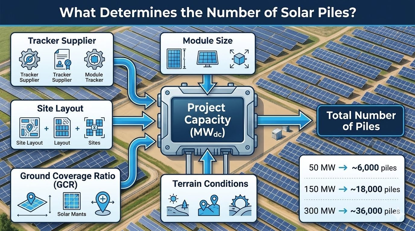
When I approach a new site, I look at the tracker supplier specifications first. The interaction between module size and tracker length dictates the tributary area per pile. If you miss the nuance of the Ground Coverage Ratio (GCR), your site layout will fail to account for inter-row shading and structural density, leading to significant cost overruns during the installation phase.
Key Takeaways for Foundation Planning:
- Project capacity in MWdc serves as the primary scaling factor for foundation procurement.
- GCR directly influences the density of trackers and, consequently, the total pile count.
- Geotechnical reports must dictate pile embedment depth, which impacts material volume even if the count remains constant.
- Linear scaling (e.g., 6,000 piles per 50 MW) provides a baseline, but site-specific terrain adjustments are mandatory.
Engineering Analysis: The Total Number of Piles
Foundation Design Parameters: The calculation of the total number of piles relies on the integration of structural load paths, soil-structure interaction, and the geometric layout of the solar array.
To determine the total number of piles, we must first establish the number of trackers required to meet the target MWdc capacity. If a single tracker supports 80 modules of 550W each, the capacity per tracker is 44 kWdc. For a 50 MWdc project, we require approximately 1,136 trackers. If each tracker design utilizes 5 piles, the base count is 5,680, which we then adjust for site-specific terrain factors.
Structural Load and Soil Interaction
In my experience, the structural integrity of the pile foundation is governed by ASCE 7 wind load requirements. We calculate the lateral and axial loads based on the maximum tilt angle of the tracker. The soil-structure interaction is modeled using the p-y curve method, ensuring that the pile embedment depth provides sufficient resistance against overturning moments.
Scaling Factors and GCR Impact
The Ground Coverage Ratio (GCR) is defined as the ratio of the module area to the total land area. A higher GCR increases the number of trackers per acre, which increases the total pile count. However, this must be balanced against the shading losses and the cost of additional steel. I typically utilize the following formula for preliminary estimation:
Total Piles = (Project Capacity / Tracker Capacity) * Piles Per Tracker * Terrain Factor
The Terrain Factor is a multiplier (typically 1.05 to 1.15) that accounts for site irregularities, such as slopes or drainage channels, which prevent the installation of standard-length piles. When designing for high-wind regions, we often increase the pile diameter or wall thickness rather than the count, but this must be verified against the IBC building codes.
Finally, consider the material specifications. Using ASTM A500 grade steel for structural piles is standard, but the coating requirements (galvanization) must be tailored to the soil corrosivity index. If the soil is highly acidic, the design life of the pile may be compromised, necessitating a thicker wall section to account for corrosion allowance over the 30-year project lifespan.
Structural Foundation Trade-offs: Selecting the optimal pile configuration involves balancing installation speed, material costs, and long-term structural reliability under varying environmental conditions.
Advantages
- Driven piles offer rapid installation rates, significantly reducing labor costs.
- High load-bearing capacity allows for fewer piles per tracker in stable soil.
- Standardized manufacturing processes ensure consistent quality and material availability.
- Minimal site disturbance compared to concrete-based foundation systems.
- Excellent resistance to lateral wind loads when properly embedded.
Disadvantages
- High sensitivity to subsurface obstructions like boulders or bedrock.
- Corrosion risk in high-salinity or acidic soil environments.
- Requires heavy machinery, which may be difficult to mobilize on steep terrain.
- Limited adjustability once the pile is driven to the refusal depth.
- Potential for pile buckling if the unsupported length is not properly calculated.
Foundation Deployment Scenarios: The application of pile foundations varies significantly based on the specific requirements of the solar installation site and the local regulatory environment.
Utility-Scale Solar Farms
In large-scale projects exceeding 100 MW, the focus is on minimizing the total number of piles to reduce procurement and logistics costs. We optimize the tracker length to maximize the tributary area per pile, ensuring that the structural design meets the stringent requirements of utility-grade infrastructure.
Brownfield Redevelopment
When installing solar on former industrial sites, the pile design must account for potential soil contamination and unknown subsurface debris. We often utilize pre-drilling or specialized helical piles to navigate these challenges while maintaining the structural integrity required for the tracker array.
High-Wind Coastal Installations
Coastal projects require enhanced structural resilience due to extreme wind loads. We increase the pile wall thickness and embedment depth to prevent foundation failure, often conducting site-specific pull-out tests to validate the design against the calculated uplift forces.
Determining the total number of piles for a solar project requires a granular understanding of how structural density correlates with site-specific capacity. In my experience, engineers must balance the mechanical load requirements of the tracker system against the geotechnical constraints of the site. The following table provides a standardized reference for estimating pile counts based on typical industry-standard tracker configurations and project scales.
These values assume a standard Ground Coverage Ratio (GCR) of 0.35 to 0.45 and typical soil conditions. Variations in tracker length, such as 2-in-portrait versus 1-in-portrait configurations, will significantly shift these baseline requirements. Always verify these estimates against the specific ASCE 7 wind load requirements for your specific project coordinates.
| Project Capacity (MWdc) | Estimated Pile Count | Piles per MWdc | Typical Tracker Type |
|---|---|---|---|
| 50 MWdc | 6,000 | 120 | Single Axis Tracker |
| 150 MWdc | 18,000 | 120 | Single Axis Tracker |
| 300 MWdc | 36,000 | 120 | Single Axis Tracker |
Note that the linear scaling observed here is a function of consistent tracker geometry. If your design incorporates longer torque tubes or higher-density module strings, the piles per MWdc ratio will decrease, though the individual pile load capacity must increase to compensate for the larger tributary area.
The following matrix maps the critical engineering entities involved in foundation design to their respective industry standards and physical parameters. Understanding these relationships is vital for maintaining structural integrity across varying site conditions. Each entity represents a specific variable in the total number of piles calculation, influencing both the quantity and the depth of the foundation elements.
By aligning these parameters with ASTM testing standards and local building codes, we ensure that the structural design remains robust against environmental stressors. This matrix serves as a quick-reference guide for project managers and structural engineers to verify that all design inputs are accounted for during the preliminary layout phase.
| Entity | Standard Reference | Primary Parameter |
|---|---|---|
| Pile Foundation | AISC 360 | Embedment Depth |
| Tracker System | ASCE 7-22 | Tributary Area |
| Soil Mechanics | ASTM D1143 | Lateral Load Capacity |
| GCR Ratio | Internal Design | Land Density |
Always cross-reference these entities with the site-specific geotechnical report. The interaction between the pile material and the soil profile is the most common point of failure in solar foundation design, necessitating rigorous adherence to the specified standards.
Before finalizing the total number of piles for a solar project, a comprehensive site verification process is mandatory. In my experience, discrepancies between the initial design layout and the actual site conditions are the primary drivers of project delays and cost overruns. This checklist ensures that all structural and geotechnical variables are validated before the first pile is driven into the ground.
- 1. Geotechnical Validation: Confirm that the soil shear strength matches the values used in the structural model per ASTM D1143.
- 2. Topographic Survey: Verify that the site slope does not exceed the tracker manufacturer’s tolerance for standard pile lengths.
- 3. Pile Load Testing: Perform pull-out and lateral load tests on at least 1% of the total pile count to validate design assumptions.
- 4. Layout Alignment: Ensure the GCR is maintained across all terrain variations to prevent row-to-row shading and structural interference.
- 5. Corrosion Protection: Verify that the galvanization thickness meets the requirements for the specific soil pH and resistivity levels found on-site.
Each of these steps acts as a safeguard against structural failure. If the site verification reveals soil conditions that are softer than anticipated, you must immediately re-evaluate the pile embedment depth or increase the total number of piles to distribute the load more effectively. Never proceed with full-scale installation until the pilot testing phase confirms the structural model’s accuracy.
In a recent 100 MWdc utility-scale project, we encountered significant challenges regarding the total number of piles required due to unexpected variations in subsurface soil density. The initial design assumed a uniform soil profile, but the actual site conditions necessitated a more complex foundation strategy to maintain structural stability.
Problem: Unexpected Soil Variability
- Soil resistivity was 30% lower than the initial geotechnical report indicated.
- Lateral load capacity was insufficient for the standard 120 piles per MWdc ratio.
- High water table levels in the northern quadrant caused pile instability during initial testing.
- Tracker alignment was compromised by uneven ground settlement.
Outcome: Optimized Foundation Strategy
- Increased the total number of piles by 15% to redistribute the load across a larger area.
- Implemented deeper pile embedment in the northern quadrant to reach stable strata.
- Adjusted the tracker spacing to maintain the required GCR despite the higher pile count.
- Achieved full structural certification under ASCE 7 standards within the revised project timeline.
The primary takeaway from this project is that the total number of piles is not a static figure but a dynamic requirement that must adapt to the physical reality of the site. I recommend conducting a more comprehensive geotechnical survey in the early stages of the project to avoid these mid-construction adjustments. Always prioritize structural integrity over initial cost estimates when site conditions are uncertain.
Frequently Asked Engineering Questions
How does project capacity influence the total number of piles?
- 50 MWdc projects typically require 6,000 piles.
- 150 MWdc projects scale to approximately 18,000 piles.
- 300 MWdc projects demand roughly 36,000 piles.
- Scaling remains near-linear, assuming consistent module technology and tracker design across the site.
What role does Ground Coverage Ratio play in pile density?
- Higher GCR values increase the number of trackers per unit area.
- Increased tracker density necessitates a higher frequency of foundation points.
- GCR must be balanced against inter-row shading losses to optimize energy yield.
- Engineers use GCR to calculate the total footprint, which determines the required structural support density across the site.
How do terrain conditions affect structural pile requirements?
- Soft soils may require deeper embedment or larger pile cross-sections.
- Sloped terrain often necessitates additional piles to maintain tracker alignment.
- Geotechnical reports are essential for determining the allowable lateral and axial loads.
- Variations in soil profile across a site can lead to non-uniform pile spacing, impacting the total count.
Why does tracker supplier choice impact foundation design?
- Different suppliers have varying tracker lengths and torque tube configurations.
- Some designs utilize single-post foundations, while others require dual-post systems.
- Supplier-provided load tables define the maximum allowable span between piles.
- Standardizing the tracker supplier early in the design phase is critical for accurate pile quantity estimation and procurement.
What is the impact of module size on pile count?
- Larger modules increase the wind sail area, requiring more robust foundation support.
- Increased module weight may necessitate closer pile spacing to prevent structural deflection.
- Tracker manufacturers adjust their pile spacing recommendations based on the specific module dimensions used.
- Engineers must verify that the chosen pile foundation can accommodate the increased moment loads associated with modern, larger-format solar modules.
Complete Course on
Piping Engineering
Check Now
Key Features
- 125+ Hours Content
- 500+ Recorded Lectures
- 20+ Years Exp.
- Lifetime Access
Coverage
- Codes & Standards
- Layouts & Design
- Material Eng.
- Stress Analysis
