Bypass Valve Engineering: Purpose, Working, and Selection Guide 2026
A Bypass Valve is a specialized piping component installed in a secondary line parallel to the main process line to ensure continuous flow, facilitate maintenance, or protect critical equipment from damage. In complex fluid systems, the Bypass Valve serves as a redundant path, allowing operators to divert flow during system start-ups, equipment failures, or routine inspections without shutting down the entire operation.
Quick Definition: What is a Bypass Valve?
A Bypass Valve is a manual or automatic valve installed in a parallel circuit (bypass loop) to redirect fluid flow around a primary component, such as a control valve, pump, or heat exchanger. Its primary engineering function is to maintain system stability, control differential pressure, and enable offline maintenance of main-line hardware.
Table of Contents
Engineering Knowledge Check: Bypass Valves
Complete Course on
Piping Engineering
Check Now
Key Features
- 125+ Hours Content
- 500+ Recorded Lectures
- 20+ Years Exp.
- Lifetime Access
Coverage
- Codes & Standards
- Layouts & Design
- Material Eng.
- Stress Analysis
The Engineering Purpose of Bypass Valves
In industrial piping design, a Bypass Valve is not merely a backup component; it is a critical instrument for operational flexibility. Whether the goal is to protect a multi-million dollar turbine or to allow a Differential pressure control technician to replace a gasket, the bypass loop ensures the facility remains online.
Pressure Regulation and Flow Balancing
Bypass valves are frequently used to manage pressure fluctuations. When a main control valve is throttled down significantly, the resulting pressure drop can create turbulence or noise. By opening a bypass line, engineers can “trim” the flow, distributing the Pressure (P) across two paths to maintain a steady downstream state. This is vital in gas distribution and high-pressure steam headers where stability is paramount.
System Start-Up, Shutdown, and Isolation
During the start-up phase of a power plant or refinery, components like steam traps and turbines are sensitive to thermal shock and water hammer. A bypass valve allows for:
- Gradual Warming: Slowly introducing hot fluid into a cold system to allow for controlled thermal expansion.
- Pressure Equalization: Reducing the differential pressure across a large isolation valve before opening it, which prevents seat damage and reduces the torque required for operation.
- Offline Maintenance: Completely isolating a primary control valve for repair without stopping the entire production line.
Critical Equipment Protection (Pumps and Compressors)
One of the most critical roles of this component is Pump minimum flow protection. Centrifugal pumps require a minimum amount of fluid moving through them to dissipate the heat generated by the impeller. If downstream demand drops to zero, the bypass valve (often an Automatic Recirculation Valve or ARC) opens to redirect fluid back to the suction tank, preventing cavitation and overheating.
Working Principle and Circuit Configurations

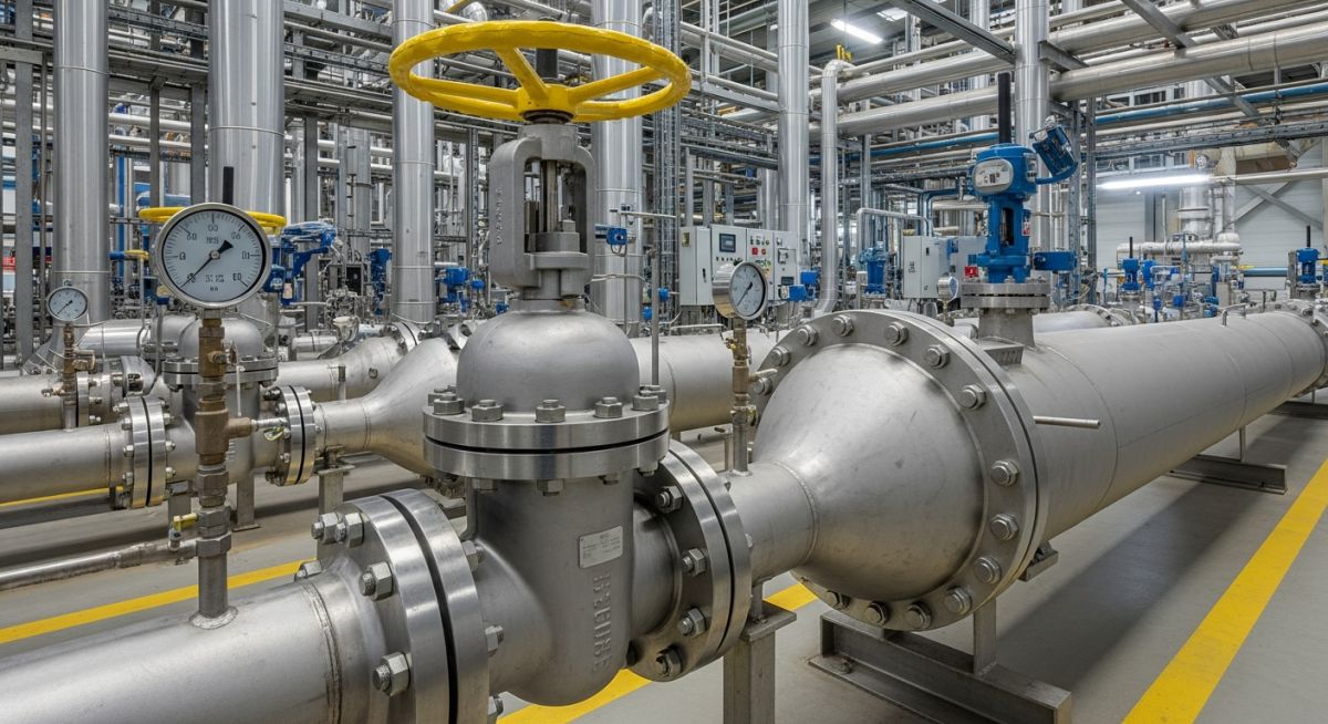
Figure 1: Typical Parallel Bypass Loop configuration showing isolation valves (Block Valves) and the central Bypass Valve.
The fundamental working of a Bypass Valve relies on the principle of “Path of Least Resistance.” In a standard installation, the main line and the bypass line are in parallel. When the bypass valve is closed, 100% of the fluid flows through the main component. As the bypass valve is opened, the fluid splits based on the flow coefficient (Cv) of each path.
Automatic vs. Manual Bypass Loops
Manual Bypass
Typically uses a Globe Valve. Operated by a technician to maintain flow during a control valve failure or for system warm-up. Requires constant monitoring of gauges.
Automatic Bypass
Driven by an actuator and a controller. It monitors Differential pressure control parameters and opens automatically when the main line pressure exceeds a setpoint.
The Physics of Differential Pressure (Delta P)
The flow rate (Q) through the bypass is determined by the pressure difference between the upstream and downstream junctions. In engineering terms, if the main line becomes restricted, the Delta P increases, forcing more fluid through the bypass line. Sizing these valves correctly involves calculating the required flow at the maximum expected differential pressure to ensure the bypass line can handle the full load if necessary.
EPCLand YouTube Channel
2,500+ Videos • Daily Updates
Valves Suitable for Bypass Service
Choosing the right hardware for a bypass loop depends on whether the primary function is throttling (regulating flow) or isolation (on/off service). Not all valves are created equal for these tasks. Below is a technical breakdown of the most common selections.
Globe Valves: The Industry Standard for Throttling
When discussing Globe valve vs Ball valve for bypass, the globe valve is almost always preferred for regulation. Its design allows for precise flow control and linear throttling. In steam systems, a globe valve in the bypass line allows operators to precisely “crack” the valve to warm up the downstream piping slowly.
Ball and Gate Valves: Isolation Efficiency
Ball Valves are excellent for quick, quarter-turn isolation. They are used in bypass loops where the intent is either “full flow” or “no flow.” However, they are poor at throttling and can suffer from seat erosion if left partially open. Gate Valves are strictly for isolation; using them in a bypass for throttling will lead to “gate chatter” and mechanical failure due to high-velocity fluid impingement.
Butterfly and Check Valves: Space and Direction
Butterfly Valves are selected for large-diameter bypass lines where space and weight are constraints, though they typically have higher leakage rates than globe valves. Check Valves are often installed in series with a bypass valve to prevent backflow into the primary line, ensuring Hydraulic recirculation loop integrity.
Comparison Table: Valve Performance in Bypass Applications
| Valve Type | Primary Use | Throttling Ability | Pressure Drop (ΔP) |
|---|---|---|---|
| Globe Valve | Flow Regulation | Excellent | High |
| Ball Valve | Quick Isolation | Poor | Very Low |
| Butterfly Valve | Large Flow Control | Moderate | Low |
| Gate Valve | System Isolation | Not Recommended | Minimal |
Engineering Standards and Sizing Calculations
A common mistake in piping design is undersizing the bypass line. For a Bypass Valve to be effective, it must be sized to handle the “Worst Case Scenario” flow of the primary line.
Sizing the Flow Coefficient (Cv)
The Control valve Cv sizing for the bypass is calculated using the following engineering formula:
Cv = Q × √(G / ΔP)
Where: Q = Flow rate (GPM), G = Specific Gravity of Fluid, ΔP = Pressure Drop (psi)
Relevant Codes (ASME and API)
Compliance is non-negotiable in 2026 industrial projects. Engineers must adhere to:
- API 6D pipeline standards: Specifies requirements for the design, manufacture, and testing of valves used in pipeline service.
- ASME B16.34: Provides the standard for valves (Flanged, Threaded, and Welding End) concerning pressure-temperature ratings.
- ASME B31.3: Governs process piping design, including the layout and safety factors of bypass loops.
Bypass Valve Sizing Calculator
Use this engineering tool to determine the required Flow Coefficient (Cv) for your bypass valve. Proper sizing ensures that the bypass line can handle the diverted flow without causing excessive backpressure or cavitation.
Bypass Valve Cv & Flow Calculator (2026 Edition)
Total fluid flow through bypass.
Water = 1.0; Diesel ≈ 0.85.
Allowable drop across the valve.
Case Study: Bypass Valve Failure Analysis in Centrifugal Pumps
Field Engineering Report | Case Ref: EP-2026-BVALVE
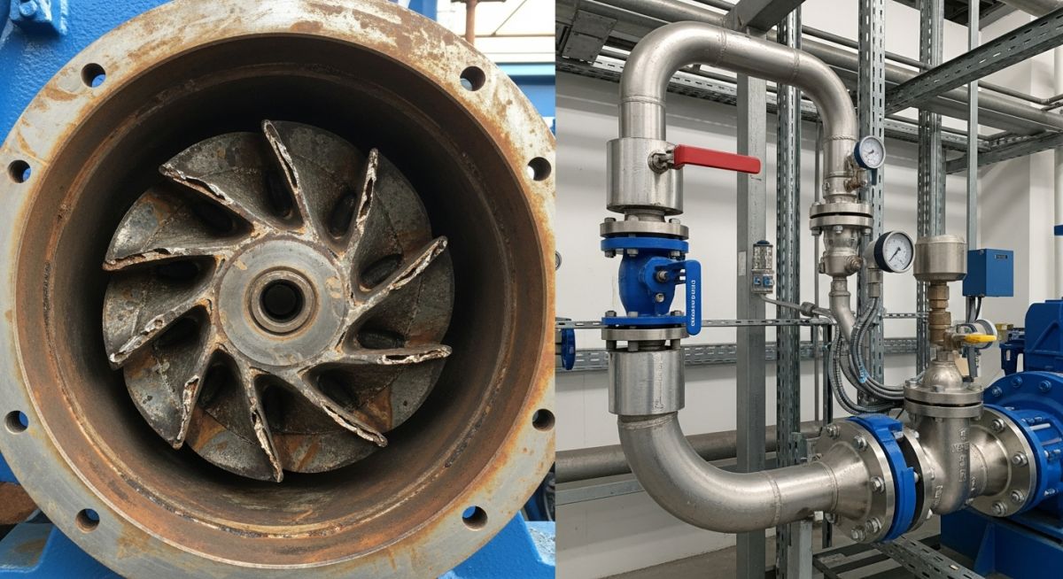
Comparison: Impeller cavitation damage (left) vs. Proper bypass recirculation loop installation (right).
Failure Context
In a large-scale Water Treatment Plant, a 500 HP centrifugal pump experienced recurring mechanical seal failures and excessive vibration. The plant operated with a variable demand system, frequently throttling the discharge valve to near-zero flow.
Root Cause:
The system lacked a dedicated Bypass Valve for minimum flow protection. When discharge was restricted, the fluid energy was converted entirely into heat (Deadheading), leading to vapor lock and cavitation.
The Engineering Fix
The Epcland Engineering team retrofitted a 3-inch Hydraulic recirculation loop using a high-recovery Globe Valve as the bypass. This allowed a constant 20% flow back to the suction tank whenever discharge demand dropped.
- • Installed an API 6D compliant bypass loop for long-term durability.
- • Integrated an automated actuator linked to the pump’s flow meter.
Estimated ROI
320% Yearly Savings
Downtime Reduction
95% Decrease
Implementation Date
January 2026
“Proper application of a Bypass Valve turned a maintenance-heavy system into a high-availability asset.” — Atul Singla, Principal Engineer.
Industrial Applications of Bypass Valves
The versatility of the Bypass Valve makes it an essential component across diverse engineering sectors. In 2026, these valves are increasingly integrated with smart sensors to optimize flow in the following scenarios:
Oil and Gas Pipelines
Used for pressure equalization across large main-line isolation valves. Without a bypass, the high differential pressure would prevent the main valve from opening or cause seat scoring.
Steam Systems
Vital for “Warming Up” steam headers. A small bypass globe valve allows steam to enter cold pipes slowly, preventing Water Hammer and catastrophic pipe failure.
Cooling Systems & HVAC
Regulates flow to chillers and heat exchangers. If the primary cooling demand drops, the bypass redirects the coolant to maintain constant pump head.
Fire Protection Systems
Ensures that fire pumps can be tested without flooding the facility by redirecting the high-pressure water back to a storage tank or suction line.
Other significant uses include Compressed Air Systems for moisture drainage and Hydraulic Systems for thermal relief and circuit testing.
Maintenance, Repair, and Troubleshooting
Because Bypass Valves are often idle until needed, they are prone to “stiction” or internal corrosion. For reliable 2026 operations, follow these maintenance protocols:
- Exercising the Valve: Periodically open and close the valve to ensure the stem moves freely and the seat is not fouled.
- Leakage Testing (Seat Tightness): Even a small bypass leak can cause significant energy loss in steam systems or process contamination.
- Packing Adjustment: Check for stem leaks, especially in valves that undergo frequent thermal cycling.
- Erosion Inspection: If used for high-pressure throttling, inspect the plug and seat for “wire drawing” or cavitation pits.
Frequently Asked Questions (FAQ)
Can I use a Ball Valve for a bypass line? ▼
What is the difference between a Bypass Valve and a Relief Valve? ▼
How is a bypass valve sized? ▼
Does every control valve need a bypass? ▼
Conclusion: Optimizing Your Piping System
The Bypass Valve remains one of the most versatile tools in an engineer’s arsenal. By understanding the specific needs of your application—whether it is Pump minimum flow protection, steam system warming, or simply facilitating offline maintenance—you can select the right valve and sizing configuration to ensure 2026 operational excellence. Always refer to API 6D and ASME standards to maintain safety and compliance across your facility.
📚 Recommended Resources: Bypass Valve

Related posts:
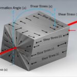
![3D engineering diagram illustrating shear modulus deformation on a solid block with force vectors.]()
Understanding Shear Modulus and Modulus of Rigidity in Piping Design
![3D render of a protective chromium oxide film forming on a stainless steel surface.]()
How Does Stainless Steel Oxide Film Formation Prevent Corrosion?
![Side-by-side comparison of industrial metal casting and metal forging processes.]()
Casting vs Forging: Key Differences for Industrial Piping Systems
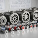
![Various types of industrial pumps displayed in a modern engineering facility.]()
Guide to Types of Pumps and Their Working Principles
![3D digital GIS map overlay showing petroleum pipeline routes across a terrain]()
Why GIS in Petroleum and Pipeline Industry is Absolutely Critical
![CAESAR II Version 14 pipe stress analysis software interface displaying a 3D piping model.]()
What Is New in CAESAR II Version 14 Pipe Stress Analysis