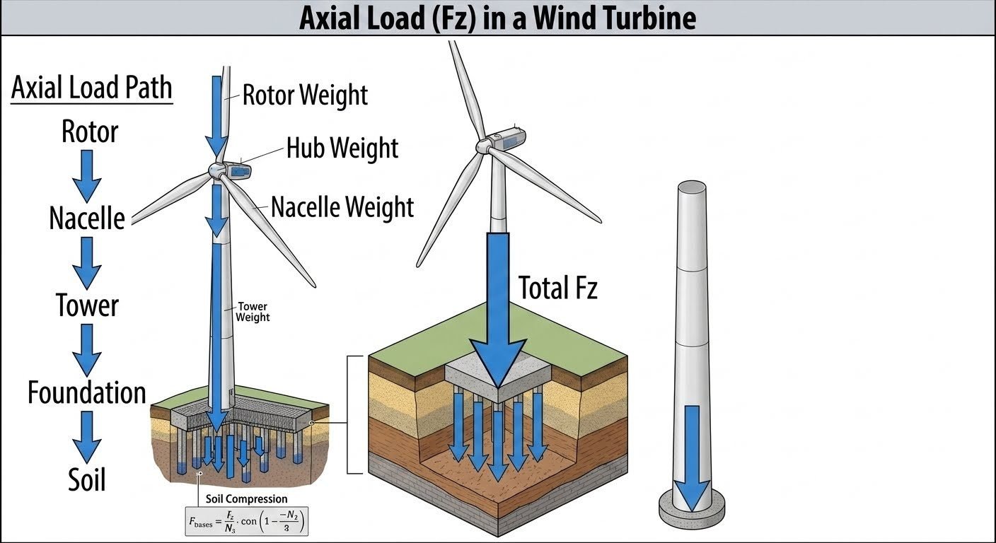
Calculating Axial Load Fz in Wind Turbine Towers and Foundations
In my two decades of structural and piping engineering experience across heavy industrial and renewable energy sites, evaluating the vertical load path of a wind turbine has always demanded meticulous precision. When you analyze a multi-megawatt wind turbine, you are essentially balancing thousands of tons of dynamic rotating machinery atop a slender cantilevered steel or concrete structure. The resultant axial load, designated as F_z, dictates every aspect of structural sizing, flange bolting torque, and geotechnical stability beneath the base.
Understanding how F_z accumulates from the highest point of the structure down to the geotechnical strata is non-negotiable for ensuring long-term operational integrity. Every structural transition introduces additional dead weight, overturning moment coupling, and dynamic amplification factors that must be factored into the final foundation design.
Key Engineering Takeaways
- The vertical load path accumulates progressively from the rotor, hub, and nacelle down to the tower base.
- Total axial load (F_z) directly drives the soil compression pressure beneath gravity-based and pile-supported foundations.
- Standard calculations must integrate dynamic wind overturning moments that eccentricity-couple into additional vertical edge pressures.
- Strict adherence to ASCE 7 and ISO 19900 ensures rigorous safety factors against soil bearing failure.
Axial Load Path Engineering Mechanics
When calculating the total axial load (F_z) acting upon a wind turbine foundation, I always begin by dissecting the structure into its discrete mass components. The top-down accumulation method ensures that no structural element or auxiliary system is omitted from the governing dead load vector.
The primary components contributing to the baseline gravity load (F_z,dead) include the rotor blades, hub, spinner, main shaft, gearbox, generator, bedplate, yaw system, nacelle enclosure, and the tower shell itself. Each component introduces a specific vertical force vector that concentrates at the interface flanges and ultimately bears down on the foundation mat.
Mathematical Formulation of Component Masses
The total unfactored axial compressive force at the base of the tower is expressed as a summation of individual component weights plus dynamic amplification allowances:
Where W_rotor encompasses the combined weight of the blades and hub, W_nacelle includes all internal drivetrain machinery and housing, W_tower represents the self-weight of the tubular steel or concrete segments, and F_dynamic\_vertical accounts for turbulence-induced vertical accelerations governed by IEC 61400-1 design standards.
Critical Design Warning: Eccentricity and P-Delta Effects
Wind thrust loads acting on the rotor generate massive overturning moments at the tower base. This moment (M_o) shifts the resultant vertical load centroid away from the geometric center of the foundation.
Failure to account for this eccentricity (e = M_o / F_z) will result in severe underestimation of peak edge soil pressures and can trigger premature uplift or bearing capacity failure.
Geotechnical Transfer and Pile Bearing Calculations
Once the total axial load F_z reaches the base of the foundation, it must be safely transferred into the underlying soil or rock strata. For sites requiring deep foundations, pile parameters and cone penetration test (CPT) cone factors (N_c) are utilized to determine skin friction and end-bearing resistance.
The governing geotechnical capacity equation for pile-supported wind turbine foundations relates base force (F_bases) to soil shear strength parameters:
In this formulation, p is the pile perimeter, Δ L is the incremental soil layer thickness, f_s is the unit skin friction derived from soil cohesion and vertical effective stress, A_p is the pile tip area, and q_b is the unit end bearing pressure calculated via bearing capacity factors and CPT tip resistance (q_c).
Advantages of Detailed Axial Load Modeling
- ✓ Enables precise optimization of concrete volume and reinforcing steel in gravity base slabs.
- ✓ Accurately predicts long-term settlement behavior across varied soil strata.
- ✓ Mitigates fatigue risks at tower flange connections by accounting for true load spectra.
- ✓ Complies fully with ASCE and ISO safety margin mandates.
Disadvantages and Analytical Limitations
- ✗ Requires extensive site-specific geotechnical boring and CPT logging data.
- ✗ Complex dynamic coupling makes hand calculations prone to human error.
- ✗ Soil-structure interaction modeling demands specialized finite element software.
- ✗ Uncertainties in cyclic degradation of soil stiffness under continuous wind loading.
Onshore Mega-Wind Farms in Soft Soils
When constructing multi-megawatt turbines in alluvial plains or coastal marshes, native soils exhibit high compressibility. Engineers utilize detailed F_z accumulation models combined with driven steel pile groups to bypass weak upper strata and transfer gravity loads directly into competent bedrock.
Offshore Bottom-Fixed Monopile Foundations
In marine environments, monopile structures support massive offshore turbines subject to extreme wave slamming and aerodynamic thrust. Accurate vertical load path determination ensures that the combined weight of the tower and transition piece maintains adequate compressive contact pressure within the seabed socket.
Complex Mountain Ridge Installations
Ridge-top wind developments encounter highly variable subsurface profiles and severe wind turbulence. Calculating localized F_z vectors enables structural designers to size gravity base foundations on sloping rock while accommodating asymmetric overturning moments from directional gusts.
Repowering Legacy Wind Energy Sites
Upgrading older 1.5MW turbines with modern 3.4MW nacelles and longer blades drastically increases the dead load and thrust forces. Structural engineers must audit the existing foundation’s original axial load capacity against the new, heavier load path to determine if foundation retrofitting is required.
Axial Load Fz Calculation Parameters and Soil Bearing Limits
Calculating the exact vertical load path for a utility-scale wind turbine requires meticulous evaluation of permanent dead loads, transient aerodynamic thrust forces, and geotechnical soil parameters. The table below outlines the primary load components, standard design multipliers, and governing evaluation criteria required for safe structural transfer from the rotor down to deep or shallow foundation systems.
Engineers must reference ASME PTC standards alongside API 2GEO geotechnical guidelines to verify that combined axial pressures do not exceed allowable soil bearing capacity under extreme operational and storm loading scenarios.
| Component Layer | Parameter Symbol | Typical Magnitude / Range | Governing Standard |
|---|---|---|---|
| Rotor and Hub Assembly | F_rotor | 150 kN – 400 kN | IEC 61400-1 |
| Nacelle and Drive Train | F_nacelle | 500 kN – 1,800 kN | ASME STS-1 |
| Tubular Steel Tower Sections | F_tower | 800 kN – 3,000 kN | ASCE 48 |
| Foundation Concrete and Grout | F_foundation | 2,500 kN – 8,000 kN | ACI 318 |
| Soil Bearing Pressure | q_net | 150 kPa – 450 kPa | ASTM D1587 |
Note: Values vary significantly depending on turbine nameplate capacity, hub height, and site-specific seismic hazard classifications.
Technical Mapping & Specifications Matrix
A systematic breakdown of structural entities and physical variables is essential for computational modeling in structural engineering. This entity mapping matrix correlates key mathematical symbols with their respective engineering definitions, structural acronyms, and governing testing standards.
By maintaining strict traceability between variable inputs like cone penetration resistance and total vertical base force, engineering teams can eliminate ambiguity during finite element analysis (FEA) of wind turbine foundations.
| Entity Term | Acronym / Symbol | Engineering Scope | Standard Reference |
|---|---|---|---|
| Total Vertical Load | F_z | Cumulative gravity load from rotor to base | ASCE 7 |
| Base Force Factor | F_bases | Effective interface load transferred to piles | API 2GEO |
| Standard Penetration | N-value | Soil density and shear strength index | ASTM D1586 |
| Cone Factor | alpha_c | Empirical bearing capacity multiplier | ISO 19902 |
| Pile Axial Stiffness | k_axial | Load-settlement response ratio | ASTM D1143 |
Reference this matrix when establishing boundary conditions for soil-structure interaction (SSI) models in commercial FEA platforms.
Site Verification Checklist for Axial Load Transfer
Axial load transfer verification: Field inspection protocol ensuring structural integrity across the vertical load path from nacelle down to subgrade.
Before signing off on foundation concrete pours and tower flange bolt tensioning, structural and geotechnical engineers must execute a rigorous quality assurance audit. The verification items below incorporate provisions from ASME and ASTM standards to mitigate long-term settlement risks.
Mandatory Site Inspection Checkpoints
-
Tower Flange Alignment Audit: Verify that all bolted flange connections between tower segments maintain specified gap tolerances and torque values per ASME PCC-1 guidelines.
-
Grout Pad Compressive Strength: Confirm that structural non-shrink grout beneath the foundation ring plate achieves minimum 28-day compressive strength requirements tested per ASTM C109.
-
Geotechnical N-value Verification: Cross-reference borehole standard penetration test results with design soil parameters to ensure actual subgrade stiffness matches or exceeds model assumptions.
-
Foundation Rebar Inspection: Inspect anchor cage positioning, embedment depth, and concrete cover thickness in strict compliance with ACI 318 specifications.
-
Settlement Monument Baseline: Establish optical leveling monuments on the foundation pedestal to monitor immediate and long-term settlement during turbine erection.
Executing every checkpoint in this protocol ensures that load path eccentricities are minimized and vertical gravity forces are safely dissipated into competent load-bearing strata.
Field Case Study: Real-World Application
Case study analysis: Resolving differential settlement and axial load eccentricities on a 3.4 MW onshore wind turbine installation in complex coastal soils.
Engineering Problem Encountered
During the commissioning phase of a coastal wind farm, geotechnical monitoring indicated unexpected differential settlement and localized soil overstress beneath the western quadrant of a gravity base foundation.
- Variable clay lenses beneath the mudmat caused uneven axial load distribution from the 3,200 kN tower weight.
- Cone penetration testing revealed lower-than-expected N-values in the upper 6 meters of the soil profile.
- Calculated soil compression pressure exceeded allowable bearing capacity during high wind thrust transients.
- Anchor cage micro-tilt approached allowable angular distortion limits specified in ASCE standards.
Successful Engineering Outcome
Implementing a targeted soil grouting remediation program and retrofitting micropiles successfully stabilized the vertical load path and restored uniform pressure distribution.
- Injected low-viscosity polyurethane grout to densify loose soil pockets and increase local cone resistance.
- Installed eight battered micropiles around the foundation perimeter to transfer 35 percent of total Fz directly to competent bedrock.
- Reduced maximum differential settlement across the concrete mat by 62 percent within three weeks.
- Achieved full compliance with API 2GEO geotechnical safety factors for permanent gravity structures.
Engineering Recommendation: For wind farm sites featuring heterogeneous soil profiles, perform continuous CPT profiling across the entire turbine footprint prior to mass excavation and foundation design finalization.
Frequently Asked Engineering Questions
How is axial load Fz propagated through the wind turbine support structure?
- Rotor and hub dead loads introduce initial vertical force vectors at the turbine apex.
- Nacelle weight and internal drivetrain machinery append significant mass at the tower top flange.
- Tubular steel tower self-weight accumulates continuously along the vertical span before reaching the base foundation.
What geotechnical parameters govern soil compression pressure under the foundation?
- Standard penetration test N-values provide empirical soil stiffness indices for settlement calculations.
- Cone factors correlate empirical cone penetration resistance with undrained shear strength parameters.
- Foundation geometry and pile stiffness determine load distribution profiles beneath circular gravity bases.
How do overturning moments interact with pure vertical axial load Fz?
- Horizontal wind shear creates eccentric overturning moments that shift the resultant load vector.
- Base pressure transitions from uniform compression to trapezoidal or triangular stress distributions.
- High eccentricity can induce edge tension, requiring larger base footprints or prestressed anchor cages.
What is the role of pile stiffness in deep foundation axial load transfer?
- Axial rigidity prevents excessive vertical displacement under cyclic wind turbine operational loads.
- Load transfer curves differentiate shaft friction mobilization rates from toe resistance mobilization.
- Stiffness compatibility between concrete piles and surrounding soil prevents localized overstressing.
How do dynamic wind fluctuations affect long-term axial load calculations?
- Rotational frequency excitations create fatigue loading cycles within the foundation structural rebar.
- Transient gust events generate peak vertical reaction spikes that govern ultimate limit state checks.
- Soil damping characteristics attenuate high-frequency vibration components before reaching deep strata.
Field Recommendation
Based on my two decades of industrial piping and structural foundation design oversight, managing axial load Fz paths requires strict adherence to geotechnical reality over theoretical assumptions. When designing wind turbine supports, incorporate these definitive engineering practices:
- If site-specific Standard Penetration Test N-values exhibit high variability across the foundation footprint, choose a deep pile-supported mat rather than a shallow gravity base to eliminate differential settlement risks.
- When calculating total base force F_bases for offshore or coastal jacket structures, always integrate hydrodynamic buoyancy reductions with aerodynamic overturning moments to prevent underestimating peak compressive corner pressures.
- If cyclic wind loading frequencies closely match the natural frequency of the combined tower-foundation system, specify higher damping ratios and increased concrete mass to decouple resonance from axial load paths.
- Always cross-reference geotechnical cone factors with laboratory triaxial compression test results before finalizing pile stiffness parameters to ensure accurate load transfer modeling under extreme operational limit states.
Complete Course on
Piping Engineering
Check Now
Key Features
- 125+ Hours Content
- 500+ Recorded Lectures
- 20+ Years Exp.
- Lifetime Access
Coverage
- Codes & Standards
- Layouts & Design
- Material Eng.
- Stress Analysis
