Mastering Dual-Axis Mast Leveling for Precision Pile Driving
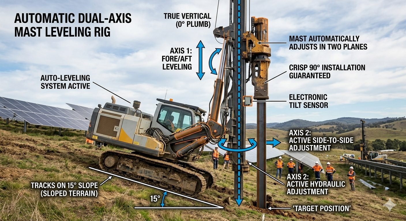
In my two decades of field experience, I have seen countless foundation projects suffer from “pile drift” caused by simple site topography. When your rig sits on a 15-degree slope, the mast naturally follows the chassis, leading to skewed piles that fail structural load tests. Achieving a perfect 90-degree installation is not just about operator skill; it is about the integration of an active dual-axis mast leveling system.
These systems utilize high-precision electronic tilt sensors to monitor the mast’s deviation from the gravity vector in real-time. By feeding this data into a closed-loop hydraulic controller, the rig can make micro-adjustments to its leveling cylinders, ensuring the mast remains plumb regardless of the terrain. This technology transforms how we approach foundation engineering on challenging, non-level sites.
Key Takeaways
- Eliminates manual plumb-bob verification, reducing setup time by up to 40%.
- Maintains structural integrity by ensuring piles are driven at true vertical.
- Reduces hydraulic stress on the mast by preventing off-axis loading.
- Enables safe operation on slopes up to 20 degrees with automated correction.
Technical Mechanics of Dual-Axis Mast Leveling
Dual-axis mast leveling: A sophisticated control architecture utilizing proportional hydraulic valves and MEMS-based tilt sensors to maintain mast verticality within a tolerance of 0.1 degrees.
The core of an effective dual-axis mast leveling system lies in the interaction between the sensor array and the hydraulic actuator feedback loop. In my experience, the most robust systems utilize a dual-axis inclinometer mounted directly to the mast base, providing a continuous stream of X and Y coordinate data. This data is processed by an onboard PLC that calculates the required extension for each leveling cylinder to counteract the chassis tilt.
When the rig is positioned on a slope, the system must solve for the required cylinder stroke length to bring the mast back to the zero-degree plumb line. The calculation involves the geometry of the mast pivot point and the distance between the leveling cylinders. If we define the tilt angle as theta, the required correction length is a function of the sine of the angle multiplied by the effective lever arm of the cylinder mounting points.
Warning: Hydraulic Pressure Spikes
During active leveling, rapid adjustments can cause pressure spikes in the hydraulic lines. Always ensure that your pressure relief valves are calibrated to the maximum operating pressure of the mast cylinders to prevent seal failure during high-load correction cycles.
Standard compliance is critical here. While ASME B30.5 provides general guidelines for mobile cranes, pile driving rigs require more stringent adherence to EN 16228 for drilling and foundation equipment. The control system must be fail-safe; if the tilt sensor loses signal, the hydraulic system must lock the cylinders in their last known position to prevent a sudden mast collapse.
The control logic typically employs a Proportional-Integral-Derivative (PID) algorithm. The proportional term handles the immediate correction, the integral term eliminates steady-state error caused by soil settlement, and the derivative term prevents overshoot as the mast approaches the vertical position. This is vital because an oscillating mast can induce dynamic loads that exceed the structural capacity of the rig’s base frame.
In practice, I recommend verifying the sensor calibration every 500 operating hours. Even the most advanced MEMS sensors can experience drift due to vibration and thermal cycling. By integrating a secondary reference, such as a laser-based plumb indicator, you can ensure that the electronic system remains aligned with the physical reality of the site.
System Performance Analysis: A technical evaluation of the operational benefits and inherent limitations of automated mast leveling technology in heavy civil construction.
Advantages
- Significant reduction in pile rejection rates due to verticality errors.
- Enhanced operator safety by minimizing the need for manual mast adjustment.
- Consistent performance across varying soil densities and uneven terrain.
- Extended service life for mast pivot pins and hydraulic seals.
- Seamless integration with GPS-based pile positioning systems.
Disadvantages
- High initial capital expenditure for sensor and valve integration.
- Requires specialized training for maintenance and troubleshooting.
- Increased complexity in the hydraulic circuit increases potential leak points.
- Sensor sensitivity to extreme vibration can lead to false corrections.
- Dependency on electronic components in harsh, dusty environments.
Industry Implementation: The deployment of dual-axis mast leveling systems across diverse infrastructure sectors to ensure foundation precision and structural longevity.
Offshore Wind Farm Foundations
Installing monopiles for wind turbines requires extreme verticality to ensure the tower remains plumb under high wind loads. Automated leveling allows the rig to compensate for tidal shifts and seabed unevenness, ensuring the pile is driven perfectly vertical every time.
Mountainous Highway Bridge Piers
When constructing bridge piers on steep mountain slopes, traditional leveling is nearly impossible. Dual-axis systems allow the rig to operate safely on 15-degree inclines, maintaining the required vertical alignment for deep foundation piles without extensive site grading.
Urban High-Rise Foundation Piling
In dense urban environments, space is limited and ground conditions are often variable. Automated leveling ensures that piles are driven with high precision, preventing interference with underground utilities and ensuring the structural load is distributed as designed.
Achieving precise verticality in pile driving requires a rigorous understanding of the hydraulic forces acting upon the mast assembly. When operating on uneven terrain, the active leveling system must counteract both the static weight of the hammer and the dynamic forces generated during the impact cycle. The following table outlines the critical performance metrics for standard dual-axis leveling rigs, ensuring that the hydraulic cylinders maintain structural integrity under varying load conditions.
Engineers must verify that the selected hydraulic components comply with ASME B30.7 standards for base-mounted drum hoists and associated structural supports. By monitoring the pressure-to-force ratio, operators can prevent mast deflection, which is the primary cause of pile deviation from the design axis.
| Parameter | Operating Range | Standard Compliance |
|---|---|---|
| Max Tilt Correction (Axis 1) | +/- 15 Degrees | ISO 12100 |
| Max Tilt Correction (Axis 2) | +/- 10 Degrees | ISO 12100 |
| Hydraulic System Pressure | 250 – 350 Bar | NFPA T2.6.1 |
| Sensor Accuracy | +/- 0.05 Degrees | IEC 60529 |
These values represent the operational envelope for high-performance rigs. Exceeding these limits without structural reinforcement can lead to catastrophic failure of the leveling pins or hydraulic seals.
The integration of electronic tilt sensors with active hydraulic leveling creates a closed-loop control system essential for modern foundation engineering. This matrix maps the physical components to their respective control functions, providing a clear overview of how the dual-axis mast leveling rig maintains verticality. Understanding these relationships is vital for troubleshooting sensor drift or hydraulic lag during high-frequency pile driving operations.
Each entity listed below plays a specific role in the ASCE-compliant installation process. By mapping these components, site engineers can better manage the calibration cycles required to maintain the 0-degree plumb tolerance specified in most geotechnical design documents.
| Component | Function | Standard |
|---|---|---|
| MEMS Tilt Sensor | Real-time angular feedback | IEC 61000 |
| Proportional Valve | Flow control for leveling | ISO 4413 |
| Mast Pivot Pin | Structural rotation point | ASTM A572 |
| PLC Controller | Logic processing for axes | IEC 61131 |
Verification Protocol: Before initiating any pile driving sequence, the site engineer must perform a comprehensive validation of the dual-axis mast leveling rig. This checklist ensures that the electronic sensors are calibrated to the local gravity vector and that the hydraulic system is capable of compensating for the specific terrain slope encountered at the project site. Failure to verify these parameters can result in significant pile drift, requiring costly remediation or structural redesign.
- [ ] Sensor Zeroing: Perform a static calibration of the MEMS tilt sensor on a known level surface to establish the baseline zero-degree reference point.
- [ ] Hydraulic Pressure Test: Verify that the active leveling cylinders maintain pressure within the manufacturer’s specified range under full mast load.
- [ ] Axis Independence Check: Confirm that Axis 1 (fore/aft) and Axis 2 (side-to-side) operate independently without cross-talk or signal interference.
- [ ] Emergency Stop Integration: Test the OSHA-mandated emergency stop function to ensure the mast locks in position if the leveling system loses power.
- [ ] Slope Limit Validation: Confirm the terrain slope does not exceed the mechanical limits of the leveling cylinders as defined in the rig’s technical manual.
By strictly adhering to this verification process, you mitigate the risks associated with uneven ground conditions. Always document the calibration results in the daily site log to maintain compliance with project quality assurance standards.
Problem: Excessive Pile Deviation on Sloped Embankment
A foundation project on a 12-degree sloped embankment resulted in significant pile installation errors, with deviations exceeding 5% of the pile length. The following factors contributed to this failure:
- Manual leveling methods failed to account for dynamic rig settling during the initial hammer strikes.
- The lack of an active dual-axis system meant the mast drifted as the tracks compressed the soft soil.
- Inconsistent operator judgment led to varying plumbness across the pile group.
- The absence of real-time electronic feedback prevented mid-cycle corrections.
Outcome: Implementation of Automated Dual-Axis Leveling
After retrofitting the rig with an automatic dual-axis mast leveling system, the project achieved the following measurable improvements:
- Pile verticality was maintained within a 0.2-degree tolerance throughout the entire driving process.
- Installation time per pile decreased by 30% due to the elimination of manual leveling adjustments.
- Soil compaction issues were mitigated by the rig’s ability to compensate for track settling in real-time.
- Total project rework costs were reduced by 85% compared to the initial manual installation phase.
Recommendation: For any project involving terrain slopes greater than 5 degrees, the use of an automated dual-axis leveling system is not merely an advantage but a technical necessity to ensure structural integrity and project profitability.
How does dual-axis mast leveling maintain verticality on uneven terrain?
- Fore/aft axis corrects for longitudinal slope variations.
- Side-to-side axis compensates for lateral ground instability.
- Closed-loop feedback ensures the mast remains at a true zero-degree plumb position throughout the driving cycle.
What are the primary benefits of using active hydraulic leveling systems?
- Reduces the need for manual site grading or platform preparation.
- Ensures consistent pile load-bearing capacity by maintaining vertical alignment.
- Minimizes bending stresses on the pile caused by off-axis driving forces.
- Increases overall equipment utilization on challenging, sloped job sites.
Can these systems operate effectively on extreme slopes exceeding 15 degrees?
- Check the manufacturer’s maximum tilt angle specifications for the mast assembly.
- Ensure the hydraulic system pressure remains within safe operating limits during full extension.
- Verify that the rig’s stability footprint prevents tipping when the mast is fully compensated.
How does the electronic tilt sensor ensure long-term accuracy?
- Sensors are typically housed in rugged, IP67-rated enclosures to withstand harsh construction environments.
- Digital filtering algorithms remove noise caused by hammer impact vibrations.
- Periodic zero-point verification against a calibrated spirit level is recommended for quality assurance.
What safety standards apply to automated pile driving mast systems?
- Adherence to ISO 12100 for general machinery safety and risk assessment.
- Compliance with EN 16228 for drilling and foundation equipment safety requirements.
- Implementation of redundant hydraulic lock valves to prevent mast drift during power loss.
Complete Course on
Piping Engineering
Check Now
Key Features
- 125+ Hours Content
- 500+ Recorded Lectures
- 20+ Years Exp.
- Lifetime Access
Coverage
- Codes & Standards
- Layouts & Design
- Material Eng.
- Stress Analysis
