ASME B31.3 Guide (2026 Edition):
Process Piping Design & SIF Changes
Why are your “safe” legacy Caesar II models suddenly failing? The answer lies in the shift to B31J and the updated Stress Intensification Factors.

What is ASME B31.3?
ASME B31.3 (Process Piping) is the international code used for the design, construction, and inspection of piping in petroleum refineries, chemical plants, pharmaceutical facilities, and cryogenic plants. Unlike its counterpart, ASME B31.1 (Power Piping), B31.3 focuses on the vast variety of fluid services found in processing industries, categorized by risk (Normal, Category D, Category M, and High Pressure).
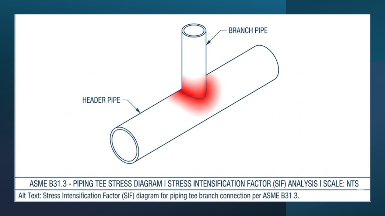
For the 2024/2026 cycle, the most critical update involves the calculation of Stress Intensification Factors (SIFs). The code has moved away from the simplified Appendix D charts, now referencing ASME B31J as the mandatory method for calculating flexibility and stress factors. This change specifically impacts how we model tees, intersections, and trunnions, often resulting in higher calculated stresses than previous editions allowed.
? B31.3 Competency Check
Test your knowledge before diving into the calculations. Can you pass the Senior Engineer check?
Loading…
Complete Course on
Piping Engineering
Check Now
Key Features
- 125+ Hours Content
- 500+ Recorded Lectures
- 20+ Years Exp.
- Lifetime Access
Coverage
- Codes & Standards
- Layouts & Design
- Material Eng.
- Stress Analysis
The “Hidden” Stress Trap: B31J vs. Appendix D
For decades, piping engineers relied on Appendix D of ASME B31.3 for calculating Stress Intensification Factors (SIFs). It was simple, chart-based, and embedded in every pipe stress software from Caesar II to AutoPIPE. However, as of the 2020-2024 cycles, ASME B31.3 has fundamentally shifted.
⚠️ The Critical Change
Appendix D has been deleted. All SIFs and Flexibility Factors (k-factors) must now be calculated per ASME B31J (Standard Method for Test and Calculation of Pipe Stress Factors).
Why does this matter? Under the old Appendix D rules, a standard welding tee often had a default SIF (Out-of-Plane) of roughly 0.75i. Under B31J, the geometry is analyzed more rigorously. In many cases, specifically for larger diameter-to-thickness ratios (D/t), the SIF increases significantly.
If you run an old model in updated software without checking the “Use B31J” toggle (or if the software forces it), you may see passing lines suddenly turn red. This is not a software bug; it is a code compliance requirement reflecting the reality that intersections concentrate stress more than we previously estimated.
Pipe Wall Thickness Calculation ($t_m$)
Before we worry about flexibility and thermal expansion, the pipe must simply hold the pressure. The hoop stress calculation in ASME B31.3 is distinct from B31.1 or B31.8.
“Design Pressure is not just the operating pressure. It is the maximum pressure coincident with the maximum temperature expected during normal operation, plus a safety margin.”
The Formula (304.1.2)
To calculate the required pressure thickness ($t$), we use the following equation. Note that this gives you the minimum required thickness for pressure only, not the final ordering thickness.
t = (P * D) / (2 * (S * E + P * Y))
Step-by-Step Example
Let’s design an 8-inch (NPS 8) line carrying steam at 600 psig and 600°F. The material is ASTM A106 Gr B (Seamless).
- P (Pressure): 600 psig
- D (Diameter): 8.625 inches (Actual OD for NPS 8)
- S (Allowable Stress): Per Table A-1, A106 Gr B at 600°F is roughly 17,900 psi.
- E (Quality Factor): 1.0 (Seamless pipe).
- Y (Coefficient): 0.4 (For Ferritic steels below 900°F).
Calculation:
t = 5175 / (2 * (17900 + 240))
t = 5175 / 36280
t = 0.1426 inches
The Mill Tolerance Trap
Do not order Schedule 10 pipe (0.148″) just because 0.1426″ < 0.148"! You must account for Mill Tolerance (manufacturing undertolerance). For seamless pipe, this is usually 12.5%.
Nominal Thickness Required ($t_{nom}$) = $t$ / (1 – 0.125)
$t_{nom}$ = 0.1426 / 0.875
$t_{nom}$ = 0.163 inches
Therefore, Schedule 10 (0.148″) is FAIL. You must upgrade to Schedule 20 (0.250″) or Standard (0.322″).
Common Quality Factors (E) & Coefficients (Y)
| Pipe Type / Spec | Quality Factor (E) | Y (Temp < 900°F) | Notes |
|---|---|---|---|
| Seamless (A106, A53 Type S) | 1.00 | 0.4 | Most common process pipe |
| ERW (Electric Resistance Weld) | 0.85 | 0.4 | Check “Additional RT” for E=1.0 |
| API 5L (Double Submerged Arc) | 0.95 | 0.4 | Large bore piping |
| Austenitic Stainless (304/316) | 1.00 (Seamless) | 0.4 | Y becomes 0.5 or 0.7 at >1050°F |
*Always verify E factors against Table A-1A or A-1B in the latest code edition.
Application: Fluid Service Categories
Design thickness is useless if you select the wrong Fluid Service category. ASME B31.3 dictates the extent of NDE (Non-Destructive Examination) based on these categories:
-
Normal
Normal Fluid Service: The default. Requires 5% Random Radiography (RT) and visual inspection. Applies to most hydrocarbons, steam, and water.
-
Category M
Category M (Toxic): Fluids where leakage causes irreversible harm (e.g., Phosgene, H2S in high concentrations). Requires 100% RT and stricter impact testing.
-
Category D
Category D: Non-flammable, non-toxic, low pressure (< 150 psig) and temp (-20°F to 366°F). E.g., Plant Air, Utility Water. Lowest NDE requirements.
EPCLand YouTube Channel
2,500+ Videos • Daily Updates
Frequently Asked Questions
What is the difference between ASME B31.1 and B31.3?
ASME B31.1 covers Power Piping (associated with power generating stations, boilers, and high-pressure steam loops), focusing on high reliability for critical plant cycles. ASME B31.3 covers Process Piping (refineries, chemical plants, pharmaceutical facilities, and cryogenic plants), offering a broader range of material options and fluid service categories to handle diverse chemical risks.
What is the mill tolerance for pipe wall thickness?
For standard seamless carbon steel pipe (like ASTM A106 or A53), the manufacturing undertolerance is 12.5%. This means a pipe ordered as “0.500 inch wall” might physically arrive as “0.4375 inch wall” and still be legal. You must subtract this 12.5% from the nominal thickness before verifying if the pipe can withstand the internal pressure.
How has ASME B31.3-2024/2026 changed regarding Stress Intensification Factors?
Recent editions have deleted the simplified Appendix D stress tables. The code now mandates the use of ASME B31J for calculating Stress Intensification Factors (SIFs) and Flexibility Factors (k-factors). This generally results in higher calculated stresses for intersections (tees/trunnions) with large Diameter-to-Thickness (D/t) ratios.
What is Category M Fluid Service?
Category M applies to fluid services where the fluid is so toxic that a single exposure to a very small quantity, caused by leakage, could produce serious irreversible harm to persons on breathing or bodily contact. Because of this risk, B31.3 mandates stricter design rules, including 100% radiography and prohibitions on certain joint types.
Conclusion: Adapting to the New Standard
Mastering ASME B31.3 in 2026 is no longer just about calculating wall thickness ($t = PD/2SE$). It requires a holistic understanding of how the code has evolved to integrate digital accuracy via ASME B31J. The days of “rule of thumb” stress analysis are fading.
Whether you are calculating the “Mill Tolerance” for a high-pressure steam line or classifying a potentially lethal chemical stream as Category M, the safety of the plant rests on your adherence to these specific paragraphs.
Next Steps for Engineers:
- Update your Stress Analysis software (Caesar II / AutoPIPE) to the latest version supporting B31J.
- Review your Pipe Class specifications to ensure Wall Thickness calculations account for the 12.5% tolerance.
- Audit your Fluid Service list to ensure no toxic fluids are wrongly categorized as “Normal.”
