
ASME B31.1 vs B31.3: The Ultimate Engineering Comparison
Navigating the complex boundary limits, safety factors, and inspection criteria between Power Piping and Process Piping codes.
The distinction between ASME B31.1 vs B31.3 is the single most common source of confusion in piping boundary definition, often leading to costly design re-works or inspection failures. While both codes fall under the ASME B31 Pressure Piping umbrella, they serve fundamentally different thermodynamic environments and risk profiles. Choosing the wrong code is not just a paperwork error; it alters the safety factor, allowable stress, and hydrostatic test pressures of your entire system.
Core Definition
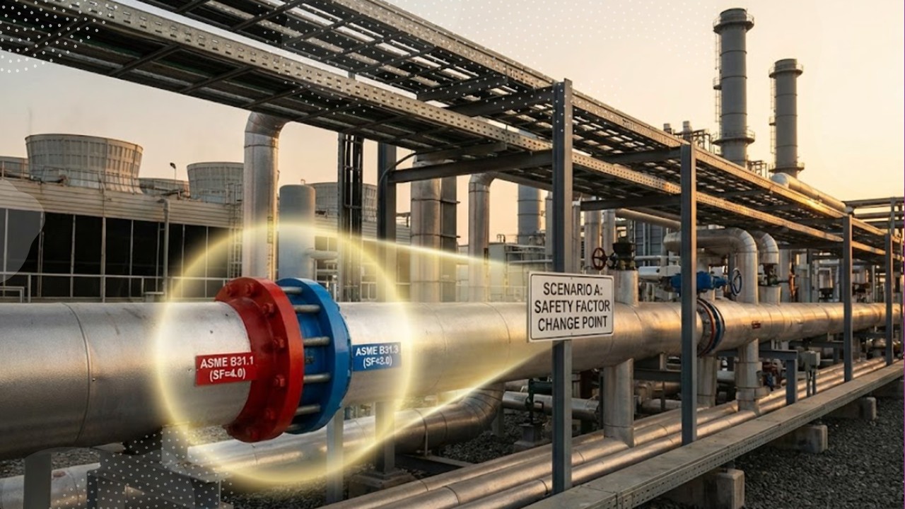
ASME B31.1 (Power Piping) governs piping associated with power generating stations, specifically focused on the steam-water cycle and district heating. It prioritizes high reliability with a conservative design margin (Safety Factor ~4:1).
ASME B31.3 (Process Piping) governs piping in refineries, chemical, pharmaceutical, and pulp mills. It accommodates a vast array of fluids and hazards with a more flexible, economical design margin (Safety Factor ~3:1).
Knowledge Check: Piping Codes
5 Questions
Complete Course on
Piping Engineering
Check Now
Key Features
- 125+ Hours Content
- 500+ Recorded Lectures
- 20+ Years Exp.
- Lifetime Access
Coverage
- Codes & Standards
- Layouts & Design
- Material Eng.
- Stress Analysis
The Fundamental Scope: Power Piping vs Process Piping
The dichotomy between ASME B31.1 vs B31.3 begins with the plant’s purpose. While both codes utilize similar formulas for hoop stress and wall thickness, their application boundaries are strictly defined by the fluid’s relationship to the energy cycle versus the product cycle.
ASME B31.1 (Power Piping) is inextricably linked to the steam-water cycle. Its jurisdiction covers fuel gas, steam, and water systems in electric power generating stations, industrial and institutional plants, geothermal heating systems, and central and district heating and cooling systems. A critical subset of this is the boiler external piping scope, which extends from the boiler proper up to the first block valve. This piping is unique because it often falls under the administrative jurisdiction of the ASME Boiler and Pressure Vessel Code (BPVC) Section I, requiring specific code stamping (PP-Stamp).
In contrast, ASME B31.3 (Process Piping) is the “catch-all” for the hydrocarbon and chemical sectors. It applies to piping typically found in petroleum refineries, chemical, pharmaceutical, textile, paper, semiconductor, and cryogenic plants. If the fluid is being processed into a product rather than being used to drive a turbine or heat a district, the Power Piping vs Process Piping debate usually ends in favor of B31.3.

Design Physics: Allowable Stress & Safety Factors
The most significant engineering deviation lies in the safety factor design margin. B31.1 is designed for longevity and reliability in a high-energy environment where failure could be catastrophic to the power grid. Consequently, it uses a more conservative safety factor of approximately **4:1** (previously 4:1, now aligned closer to 3.5:1 in modern iterations but historically stricter) based on the ultimate tensile strength.
B31.3, recognizing the need for economic viability in massive refinery networks, operates with a safety factor of **3:1**. This means that for the exact same material and operating conditions, B31.3 might allow a thinner wall thickness than B31.1. When calculating the ASME B31.1 vs B31.3 allowable stress, engineers must pull data from *Stress Table A* (B31.1) or *Stress Table A-1* (B31.3), and the values will differ even for identical ASTM materials (e.g., A106 Gr. B).
Wall Thickness Physics
The base formula for internal pressure design appears similar, but the allowable stress variable (S) drives the result.
t = (P × D) / [2 × (S × E + P × Y)]
- t = Minimum Required Wall Thickness
- P = Internal Design Pressure
- D = Outside Diameter
- S = Allowable Stress Value (Code Specific)
- E = Quality Factor
- Y = Coefficient (Material/Temp dependent)
Testing Protocols & Inspection Criteria
Once fabrication is complete, the validation phase reveals sharp contrasts. The hydrostatic test pressure calculation is a prime example. Under ASME B31.3, the standard hydrotest pressure is **1.5 times the design pressure**, adjusted for temperature ratios. However, ASME B31.1 mandates a hydrotest at **1.5 times the design pressure** but has specific clauses regarding the “boiler external piping” which may align with Section I rules (1.5x MAWP).
Furthermore, the visual examination acceptance criteria in B31.3 are categorized by “Fluid Service” (Normal, Category D, Category M, High Pressure). A pipe carrying non-toxic water (Category D) has very loose inspection rules compared to a lethal gas line (Category M). B31.1 does not use these fluid service categories; instead, it applies a high baseline standard across the board, reflecting the critical nature of steam systems.
Master Comparison Data: B31.1 vs B31.3
| Feature | ASME B31.1 (Power) | ASME B31.3 (Process) |
|---|---|---|
| Primary Scope | Power Stations, District Heating, Boiler External Piping | Refineries, Chemical Plants, Pharma, Paper Mills |
| Design Margin (Safety Factor) | Conservative (~3.5 to 4:1) | Flexible (~3:1) |
| Allowable Stress Basis | Lower Allowable Stress (Thicker walls usually required) | Higher Allowable Stress (Thinner walls permitted) |
| Fluid Service Categories | Not Applicable (One strict standard) | Yes (Normal, Cat D, Cat M, High Pressure, High Purity) |
| NDT / Examination | Mandatory NDE for specific pressures/temps over 750°F | Based on Fluid Service (e.g., 5% random RT for Normal Fluid) |
| Calculation Protocol | Focus on sustained loads & thermal expansion | Complex fatigue analysis & flexibility factors |
*Always refer to the latest code edition for specific allowable values.
Case Study: ASME B31.1 vs B31.3 Failure Analysis
The “First Block Valve” Boundary Violation
Incident Data
- Facility: 850MW Cogeneration Plant (Texas)
- System: High-Pressure Boiler Feedwater
- Operating Pressure: 2,200 psig @ 350°F
- Failure Mode: Cyclic Fatigue Crack
- Cost Impact: $1.2M (Unplanned Outage)
The Jurisdictional Error
During a capacity expansion project, an EPC contractor extended the piping design from the water treatment plant (B31.3 jurisdiction) directly to the boiler inlet. The design team failed to recognize the Boiler External Piping (BEP) scope, which mandates that all piping between the boiler and the first block valve must adhere to ASME B31.1 and technically falls under the administrative control of ASME Section I.
The contractor utilized the ASME B31.3 allowable stress tables for ASTM A106 Gr. B carbon steel. At the design temperature, B31.3 permitted a higher allowable stress (approx. 20.0 ksi) compared to the more conservative B31.1 limit (approx. 15.0 ksi). Consequently, the calculated wall thickness was determined to be Schedule 80, whereas B31.1 protocols would have mandated Schedule 100 or 120 to satisfy the safety margins.
Root Cause: Safety Factor Mismatch
The failure was not an immediate burst but a fatigue crack developed over 14 months. The safety factor design margin in B31.1 is specifically tuned to handle the vibration and sustained loads characteristic of power generation cycles (steam hammer, turbine trips). By using the B31.3 logic, which utilizes a 3:1 safety margin geared towards chemical compatibility and flexibility, the pipe lacked the necessary rigidity and thickness to dampen the pump-induced harmonics.
Furthermore, the visual examination acceptance criteria applied during construction were based on B31.3 “Normal Fluid Service,” which allows for random spot radiography (5%). Had B31.1 been applied, the BEP status would have likely triggered 100% volumetric examination (RT/UT) for these pressures, potentially catching the weld root defect that eventually propagated into the failure shown in Figure 2.
Corrective Action & ROI
The facility replaced the compromised spool with Schedule 120 pipe compliant with ASME B31.1. The design package was re-stamped with the “PP” symbol (Power Piping) as required by the National Board.
EPCLand YouTube Channel
2,500+ Videos • Daily Updates
Frequently Asked Questions: B31.1 vs B31.3
Can I use ASME B31.3 for Power Plant piping?
Generally, no. If the piping is part of the steam-water cycle in a power generation station (Power Piping), it falls under ASME B31.1. However, auxiliary systems in a power plant (like lube oil, air, or water treatment) may be designed to ASME B31.3 if designated by the owner, provided they do not fall within the specific boiler external piping scope which is strictly regulated.
How does the hydrostatic test pressure calculation differ?
The hydrostatic test pressure calculation in ASME B31.3 is typically 1.5 times the design pressure, adjusted by the ratio of allowable stresses at test temperature vs. design temperature (unless this exceeds yield strength). ASME B31.1 also mandates 1.5 times the design pressure but is often more rigid regarding the Boiler External Piping, which must align with Section I requirements (1.5 times MAWP).
Which code is safer: B31.1 or B31.3?
“Safer” is subjective, but ASME B31.1 is more conservative. It utilizes a higher safety factor design margin (historically 4:1) compared to B31.3 (3:1). This results in thicker pipe walls for the same pressure. B31.1 assumes a longer life cycle with high reliability for public safety (power grids), while B31.3 balances safety with the economic reality of complex, replaceable process loops.
Does B31.3 allow lower quality materials?
Not lower quality, but B31.3 allows a broader range of materials. Because Process Piping handles everything from cryogenic fluids to lethal acids, B31.3 provides extensive data for exotic alloys, non-metallics, and thermoplastics. B31.1 focuses heavily on Carbon and Alloy steels proven for high-temperature steam service.
Final Engineering Verdict
The choice between ASME B31.1 vs B31.3 is never about preference—it is about jurisdiction and physics. Misapplying these codes can lead to catastrophic failure or illegal non-compliance. Always verify the “First Block Valve” boundary and respect the distinct safety margins of Power Piping vs Process Piping.
© 2026 Epcland Engineering. All rights reserved. | Privacy Policy

Related posts:
![A mechanical sucker rod pumpjack operating in an oil field at sunset]()
What is Sucker Rod Pump System in Oil Production?
![Piping material engineer reviewing technical specifications on a tablet in an industrial plant.]()
How a Piping Material Engineer Drives Industrial Project Success
![Industrial refinery plant showing various types of static equipment]()
What is Static Equipment? Types and List of Static Equipments
![Side-by-side comparison of industrial process piping and power plant steam piping systems.]()
Differences Between ASME B31.3 and B31.1: B31.3 vs B31.1
![Large industrial steel storage tank under construction with cranes and scaffolding]()
Storage Tank Construction Method Statement: Step-by-Step Engineering Guide
![Cutaway diagram of a globe control valve highlighting the internal valve trim components]()
What is a Valve Trim? Types, Components, and Selection


