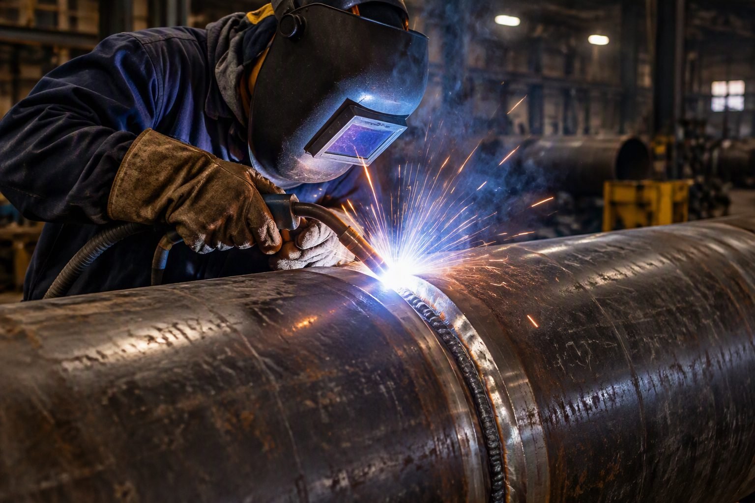
Mastering ASME B16.11 Butt-Weld Limits and Socket Weld Transition Criteria
When walking through a high-pressure fabrication workshop, I frequently inspect the critical transition boundary where small-bore socket weld fittings end and large-diameter butt-weld components begin. For over two decades as a piping engineering expert, I have seen junior designers stumble over the rigid size thresholds enforced by ASME B16.11. Understanding these geometric boundaries is not merely an academic exercise; it is a mandatory safety requirement that directly dictates the structural integrity of process plants handling hazardous hydrocarbons.
Socket-welded fittings under ASME B16.11 are strictly restricted to specific nominal pipe sizes due to thermal fatigue limitations and crevice corrosion vulnerabilities. When piping geometry exceeds the 2-inch threshold, fabrication codes mandate an immediate shift toward butt-welded configurations covered by ASME B16.9 and ASME B31.3. This transition eliminates stress risers, ensures full-penetration joint efficiency, and accommodates severe cyclic thermal loads without premature cracking.
Key Engineering Takeaways
- Socket-weld fittings under ASME B16.11 are functionally restricted to NPS 2 and smaller.
- Sizes above NPS 2 require full-penetration butt-welding per ASME B16.9 to mitigate fatigue failure.
- Proper root gap management and bevel preparation are vital for high-pressure service compliance.
ASME B16.11 Butt-Weld Engineering Principles and Size Limits
In my design reviews, I frequently encounter piping layouts where designers mistakenly specify socket-welded unions for lines exceeding 2 inches nominal pipe size. ASME B16.11 governs forged fittings, including socket-welding and threaded types, but its structural scope is practically bounded by thermal fatigue constraints in larger diameters. When pipe sizes scale up, the socket expansion joint creates an unavoidable 1/16-inch minimum expansion gap that acts as a crevice, trapping corrosive process fluids and inducing severe localized bending stresses under cyclic thermal expansion.
To prevent catastrophic joint failure in high-pressure hydrocarbon processing units, piping codes mandate that any line operating under severe cyclic conditions or exceeding NPS 2 transition to butt-welded fittings designed under ASME B16.9 or ASME B16.11 socket-weld alternatives must be strictly evaluated. The butt-weld joint configuration provides a smooth internal contour, matching the inner diameter of the mating pipe exactly when properly bored, which eliminates flow turbulence and pressure drop spikes.
Socket Weld Size Restrictions and Fatigue Limits
Socket-weld fittings rely on a fillet weld deposited at the hub of the fitting where it overlaps the inserted pipe end. Unlike a butt weld, which achieves 100 percent joint efficiency through full-thickness penetration, a socket weld achieves approximately 50 percent nominal strength relative to the connected pipe wall. Furthermore, differential thermal expansion between the pipe wall and the socket hub creates high localized stress concentrations at the toe of the fillet weld during thermal transients.
When piping systems undergo frequent startup and shutdown cycles, these localized stresses exceed the endurance limit of standard carbon steel and alloy steel socket joints. Consequently, ASME B31.3 restricts socket-welded components in severe cyclic service and strongly recommends shifting to butt-welded fittings for all lines NPS 2 and larger. Failing to observe this limit results in accelerated vibration-induced fatigue cracking right at the weld toe.
Critical Design Warning: Socket Weld Crevices
Never utilize socket-welded fittings in services subject to severe external vibration, caustic stress corrosion cracking, or lethal fluid containment where crevice corrosion can rapidly breach the pressure boundary.
- Mandatory 1.5mm (1/16-inch) expansion gap required before welding to prevent bottoming out.
- Prohibited in lethal services per ASME B31.3 Chapter VI.
- Prone to accelerated crevice corrosion in wet sour gas and amine treating units.
Transitioning to ASME B16.9 for Large Diameter Systems
Transitioning from small-bore forged fittings to large-diameter butt-welding components requires meticulous attention to wall thickness matching and bevel geometry. When connecting an ASME B16.9 elbow or tee to a pipe with differing nominal wall thicknesses, internal or external tapering must comply with ASME B31.3 misalignment limits. A mismatch exceeding 1.5 millimeters without proper boring or tapering introduces severe eddy currents and localized erosion-corrosion.
Certified welders executing butt-weld joints must perform root passes using Gas Tungsten Arc Welding (GTAW) to ensure complete penetration and a smooth, oxidation-free root bead. Subsequent fill and cap passes using Shielded Metal Arc Welding (SMAW) or Gas Metal Arc Welding (GMAW) provide the required mechanical strength and impact toughness. Non-destructive examination (NDE) via radiography or ultrasonic testing is then deployed to verify the absence of volumetric defects.
Advantages
- Achieves 100 percent joint efficiency with full-penetration butt-welding.
- Eliminates internal crevice corrosion sites inherent in socket-weld gaps.
- Provides smooth internal flow contours, minimizing pressure drop and turbulence.
- Exhibits superior resistance to severe thermal fatigue and mechanical vibration.
- Complies fully with ASME B16.9 and ASME B31.3 for high-pressure systems.
- Facilitates straightforward volumetric non-destructive examination (NDE).
Disadvantages
- Requires highly certified welding personnel and rigorous root pass controls.
- Involves significantly higher fabrication and labor costs compared to socket welding.
- Demands extensive post-weld cleaning and internal purging for alloy materials.
- Longer installation turnaround time in congested modular fabrication yards.
- Requires precise bevel preparation and alignment tooling to prevent high-low mismatch.
- Mandates comprehensive radiographic or ultrasonic testing for quality verification.
High-Pressure Hydrocarbon Refining Units
In catalytic reforming and hydrotreating process loops, operating pressures regularly exceed 150 bar at elevated temperatures. Piping engineers strictly specify butt-welded fittings and piping transitions to withstand severe thermal cycling and prevent catastrophic containment breaches.
Full-penetration welds ensure that hydrogen embrittlement and high-temperature creep do not initiate at joint discontinuities.
Supercritical Power Generation Steam Lines
Main steam headers in ultra-supercritical power plants operate at extreme temperatures where socket welds would fail rapidly due to thermal fatigue. Utilizing heavy-wall ASME B16.9 butt-weld elbows and tees guarantees structural stability.
Precise thermal expansion management and rigorous post-weld heat treatment (PWHT) are mandatory for these alloy steel installations.
Offshore Subsea Production Manifolds
Subsea production systems endure immense external hydrostatic pressure combined with internal flow turbulence from multi-phase hydrocarbons. Butt-welded piping architecture eliminates crevice corrosion sites that are vulnerable to seawater ingress and aggressive chemical treatments.
Every welded joint undergoes 100 percent volumetric NDE to ensure zero defect tolerance before subsea deployment.
Cryogenic Liquefied Natural Gas Processing
LNG liquefaction trains operate at minus 162 degrees Celsius, where austenitic stainless steels experience severe embrittlement risks if joint geometry induces stress concentrations. Butt-weld fittings provide uninterrupted flow paths and preserve impact toughness.
Welding procedures require controlled heat input to prevent carbide precipitation and intergranular corrosion in low-temperature service.
Chemical Synthesis and Acid Transfer Plants
Handling highly corrosive chemical media requires seamless integration of corrosion-resistant alloy piping components. Butt-weld joints prevent stagnant pockets where chemical crystallization and localized pitting corrosion could initiate.
Smooth internal purging during welding prevents root oxidation and preserves the passive protective oxide film of the alloy.
ASME B16.11 and ASME B16.9 Dimensional and Rating Parameters
Selecting the correct fitting standard for industrial piping systems requires a rigorous understanding of size boundaries, pressure ratings, and connection types governed by ASME codes. While ASME B16.11 standardizes forged fittings for socket-welding and threading up to 4 inches, practical limitations in fabrication and code design typically restrict socket welds to NPS 2 and smaller. Beyond this threshold, thermal stresses and crevice corrosion risks necessitate transitioning to butt-welded components governed by ASME B16.9.
The following engineering data table provides a comparative breakdown of sizing ranges, pressure-temperature ratings, and applicable joining standards for industrial piping designers. Review these parameters carefully to ensure seamless transitions between forged and wrought components across severe service process units.
| Parameter / Feature | ASME B16.11 Socket Weld | ASME B16.11 Threaded | ASME B16.9 Butt-Weld |
|---|---|---|---|
| Standard Size Range | NPS 1/8 to 4 (Practical limit NPS 2) | NPS 1/8 to 4 | NPS 1/2 to 48 and larger |
| Pressure Classes | Class 3000, 6000, 9000 | Class 2000, 3000, 6000 | Matched to pipe schedule (Sch 10 to XXS) |
| Primary Joining Method | Fillet weld with 1.5mm expansion gap | Tapered pipe threads (NPT / ASME B1.20.1) | Full penetration groove butt-weld |
| Crevice Corrosion Risk | Present in socket annulus | High in threaded root threads | None (smooth internal bore transition) |
| Nondestructive Examination | Magnetic Particle or Liquid Penetrant | Visual inspection and pressure testing | Radiographic Testing or Ultrasonic Testing |
Note: Pressure-temperature ratings for forged fittings decrease linearly as operating temperatures approach the maximum allowable creep range defined in ASME B31.3.
Technical Mapping & Specifications Matrix
Executing complex hydrocarbon and power piping projects requires seamless data mapping between material specifications, design codes, and fabrication standards. When transitioning from forged socket-weld components to full-penetration butt-weld systems, piping engineers must align metallurgical grades, wall thicknesses, and inspection criteria to prevent premature joint failure under cyclic fatigue.
The entity matrix below establishes the core structural relationships, acronyms, and governing criteria utilized throughout the engineering lifecycle of high-pressure piping assemblies. Each entry cross-references primary international standards to ensure absolute compliance during detail design and shop fabrication.
| Entity / Acronym | Full Technical Description | Governing Standard | Engineering Application Scope |
|---|---|---|---|
| NPS | Nominal Pipe Size | ASME B36.10M | Standardized dimensionless designator for pipe dimensions |
| HAZ | Heat Affected Zone | AWS D1.1 / ASME Sec IX | Metallurgical alteration zone adjacent to the weld fusion line |
| RT / UT | Radiographic / Ultrasonic Testing | ASME Sec V | Volumetric nondestructive examination for butt-weld integrity |
| P-Number | Base Metal Grouping Designation | ASME BPVC Section IX | Categorization of ferrous alloys for welding procedure qualification |
| MT / PT | Magnetic Particle / Liquid Penetrant | ASME Sec V | Surface examination for socket welds and fillet connections |
Site Verification Checklist for Large Diameter Butt-Weld Joints
Executing high-integrity butt-weld joints above 2-inch nominal pipe size demands strict adherence to shop fabrication protocols and field assembly verifications. Piping inspectors must systematically review joint fit-up, root gap dimensions, bevel angles, and welding procedure specifications before any arc is struck. Omitting any single verification step can introduce root defects, high residual stresses, or premature structural failure under operating thermal cycles.
Use the comprehensive engineering checklist below to audit fabrication yard operations and field construction sites prior to final welding and non-destructive examination sign-off.
Fabrication Yard and Field Quality Assurance Checkpoints
- Material Traceability: Verify mill test reports against pipe and fitting heat numbers for compliance with ASTM material specifications and project piping class requirements.
- Bevel Angle Verification: Measure preparation angles using a dedicated weld gauge to confirm conformity with the qualified welding procedure specification (WPS).
- Root Opening and High-Low: Check internal alignment and root spacing to ensure smooth fluid flow transition and prevent turbulence-induced erosion.
- Preheat Temperature Control: Monitor base metal temperature using calibrated thermocouples or tempilstik crayons when welding thick-wall carbon steel per ASME B31.3 requirements.
- Interpass Cleaning: Ensure slag and oxide scale are thoroughly removed between weld passes using stainless steel wire brushes to prevent inclusions.
- Post-Weld Heat Treatment (PWHT): Verify thermocouple placement, heating rate, soak time, and cooling rate charts for alloy or heavy-wall carbon steel joints.
- Final NDE Clearance: Confirm that radiographic or ultrasonic examination reports are signed off by certified Level II/III inspectors prior to hydrostatic pressure testing.
Action Rule: Any non-conformance identified during checklist verification must be quarantined, documented on a non-conformance report (NCR), and dispositioned by the lead piping engineer before hydrostatic testing proceeds.
Field Case Study: Real-World Application
A severe vibration issue occurred in a high-pressure compressor station when socket-weld fittings were improperly specified on 3-inch bypass piping operating under severe reciprocating pressure fluctuations.
Engineering Problem Analysis
The construction contractor utilized socket-weld fittings above the 2-inch nominal size limit in an attempt to accelerate schedule, resulting in severe structural fatigue failures within six months of commissioning.
- Exceeded maximum practical size limits for socket welds defined in ASME B16.11 guidelines.
- Concentrated high cyclic bending stresses at the unreinforced toe of the fillet welds.
- Induced crevice corrosion and accelerated fatigue cracking within the internal socket annulus.
- Ignored mechanical vibration resonance frequencies generated by reciprocating compressor harmonics.
Successful Engineering Remediation
The engineering team re-engineered the entire 3-inch bypass piping spool by replacing all socket-weld components with ASME B16.9 butt-weld elbows, tees, and full-penetration groove welds.
- Eliminated stress concentration nodes by providing smooth, uniform internal bore transitions.
- Achieved 100 percent volumetric inspection clearance via radiographic testing (RT).
- Successfully passed hydrostatic pressure testing at 1.5 times design pressure without leakage.
- Extended operational service life beyond design thresholds, eliminating unscheduled downtime.
Engineering Recommendation: Always enforce strict adherence to the 2-inch socket-weld threshold. For any piping system operating above NPS 2 or subject to severe thermal and mechanical fatigue, mandate ASME B16.9 butt-weld connections backed by rigorous quality control.
Frequently Asked Engineering Questions
Why does ASME B16.11 not cover butt-weld fittings above 2 inches?
ASME B16.11 specifically governs forged socket-welding and threaded fittings, which are historically limited to small-bore piping.
- Socket welds above 2 inches present severe volumetric inspection challenges via radiography.
- Thermal expansion stresses create high fatigue risks at the socket weld root.
- Large-bore systems require the full-penetration reliability of ASME B16.9 butt-weld fittings.
What is the primary difference between ASME B16.11 and ASME B16.9?
These two standards govern entirely different fitting geometries and joining methods for industrial piping systems.
- ASME B16.11 covers forged socket-weld and threaded fittings up to 4-inch nominal size.
- ASME B16.9 covers factory-made wrought butt-welding fittings from 1/2-inch to 80-inch diameters.
- Butt-welded joints provide a smooth internal flow profile, minimizing turbulence and erosion compared to socket configurations.
Can you use socket weld fittings for high-pressure hydrogen service?
I strongly advise against using socket-welded fittings in high-pressure hydrogen or hazardous chemical services.
- The inherent crevice between the pipe end and the socket bottom acts as a stress riser.
- This crevice accumulates corrosive agents, accelerating hydrogen embrittlement and stress corrosion cracking.
- Industry codes like ASME B31.3 restrict socket welds in severe cyclic conditions.
How do you transition from a socket weld to a butt-weld system?
Transitioning requires a clean spec break and the correct selection of piping components.
- Use a piping spec break at the 2-inch boundary, switching from socket-weld to butt-weld.
- Employ reinforcing branch connections or reducing butt-weld tees for size transitions.
- Ensure the pipe wall thickness schedule matches between the fitting and the run pipe.
What is the required gap for an ASME B16.11 socket weld before welding?
Fit-up standards require a specific minimum clearance to prevent weld cracking during thermal contraction.
- A 1/16-inch (1.6 mm) minimum gap must be established between the pipe end and the socket shoulder.
- Welding without this gap causes the expanding pipe to bottom out, cracking the fillet weld.
- Contractors often use consumable spacer rings to guarantee this gap during workshop fabrication.
How does NDT differ between socket welds and butt-welds?
Non-destructive testing methods vary significantly due to the joint geometry and risk profiles.
- Butt-welds allow full volumetric inspection using radiography (RT) or ultrasonic testing (UT).
- Socket welds are limited to surface examinations like magnetic particle (MT) or liquid penetrant (PT) testing.
- The lack of volumetric inspection makes socket welds unsuitable for critical high-pressure lines.
Field Recommendation
- If your piping system operates under severe cyclic loading or temperatures exceeding 400°F (204°C), I recommend bypassing socket welds entirely—even for lines under 2 inches—and utilizing full-penetration butt-welds to eliminate root-crack propagation risks.
- When transitioning from small-bore ASME B16.11 fittings to large-bore ASME B16.9 systems, always specify a minimum 1.5-times pipe diameter straight run before any change in direction to stabilize flow turbulence and prevent localized erosion.
- In my experience, you should mandate the use of visual gap-o-let rings or scribe lines during fit-up of socket welds; this simple workshop practice prevents welders from bottoming out the pipe, which is the leading cause of premature fillet weld failures.
- If you are designing for highly corrosive or sour services (such as NACE MR0175 compliance), select butt-welded joints over socket welds regardless of pipe size to eliminate the crevice corrosion cell inherent to socket configurations.
Complete Course on
Piping Engineering
Check Now
Key Features
- 125+ Hours Content
- 500+ Recorded Lectures
- 20+ Years Exp.
- Lifetime Access
Coverage
- Codes & Standards
- Layouts & Design
- Material Eng.
- Stress Analysis
