What Are As-Built Drawings and How Do They Differ?
In my 20-plus years of managing large-scale piping and EPC projects, I have seen millions of dollars wasted simply because someone assumed the physical plant matched the original design blueprints. It rarely does. During construction, field interferences, material shortages, and unexpected soil conditions force engineers to make real-time adjustments. If these changes are not documented, the facility’s long-term safety and operational efficiency are severely compromised.
This is where the transition from design intent to physical reality becomes critical. Understanding the exact differences between construction drawings and final records is not just an administrative task; it is a fundamental safety requirement governed by codes like ASME B31.3 and API 570.
Key Takeaways for Project Managers
- Design vs. Reality: Construction drawings show what should be built, while final records show what was actually built.
- Regulatory Compliance: Accurate records are mandatory for safety audits, environmental permits, and insurance validation.
- Asset Lifecycle: Operations and maintenance teams rely entirely on these documents for safe isolation and troubleshooting.
- Risk Mitigation: Undocumented field changes can lead to catastrophic failures during high-pressure hydrotesting.
Why Are As-Built Drawings Critical for Engineering Projects?
As-Built Drawings: These final records serve as the definitive legal and technical baseline for facility operations, maintenance, and future expansions, ensuring compliance with ASME B31.3 and local building codes.
When a piping system is designed, stress engineers perform extensive calculations to ensure thermal expansion, seismic loads, and internal pressures do not exceed the allowable stress limits of the material. However, if the field installation deviates from the design isometric without being updated in the stress model, the actual stresses can exceed safe limits.
The Mathematics of Field Deviations
Consider a 10-inch carbon steel line (ASTM A106 Gr. B) operating at 350 degrees Celsius. The original design specified a 3-meter expansion loop to absorb thermal expansion. During construction, a structural column interference forced the field crew to reduce the loop width to 2.2 meters.
The displacement stress range (SE) in a piping system is calculated using the following formula:
Where:
• Sb = Resultant bending stress (MPa)
• St = Torsional stress (MPa)
By reducing the expansion loop width from 3 meters to 2.2 meters, the flexibility of the loop decreased significantly. This modification increased the resultant bending stress (Sb) from 110 MPa to 185 MPa. Under ASME B31.3 Section 319.4.4, the allowable displacement stress range (SA) for this material was 150 MPa. Because this field change was not analyzed and documented, the line operated in an overstressed condition, leading to premature fatigue cracking at the elbow weld within 18 months of commissioning.
Never allow field modifications to proceed without a formal Management of Change (MOC) process. Even minor deviations in support locations or valve orientations can alter the natural frequency of the piping system, leading to severe vibration and mechanical failure.
How to Create Accurate As-Built Drawings on Site
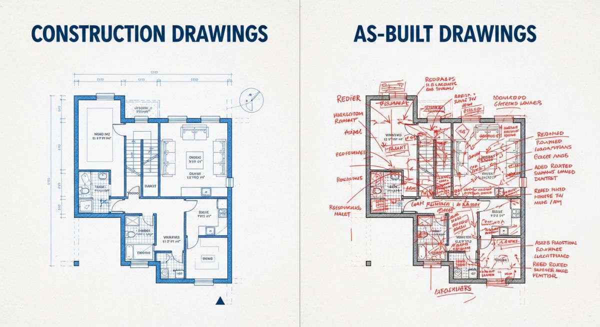
As-Built Drawings: The systematic process of drafting these records involves field-verifying physical dimensions, redlining original construction plans, and updating 3D BIM models to reflect actual spatial coordinates.
Creating these documents requires a structured approach. In my experience, relying on memory or hand-written notes taken days after the installation is a recipe for disaster. The process must be integrated into the daily construction workflow.
Step 1: Redline Markup Protocol
During construction, the field engineer or supervisor must maintain a master set of Issued for Construction (IFC) drawings on site. Any deviation must be marked immediately using a standardized color-coding system:
- Red: Additions or new installations not shown on the original design.
- Green: Deletions or components that were omitted during construction.
- Blue: Dimensional corrections, specification changes, or notes.
Step 2: 3D Laser Scanning (LiDAR)
For complex process plants, manual measurements are often insufficient. I highly recommend utilizing terrestrial 3D laser scanning. This technology captures millions of data points (point clouds) with millimeter-level accuracy. The point cloud is then overlaid onto the original 3D CAD model to automatically detect deviations that exceed specified tolerances.
As-Built Drawings: The comparative analysis highlights how design intent documents transition into physical reality records, detailing differences in ownership, accuracy tolerances, and regulatory compliance.
| Parameter | Construction Drawings (IFC) | As-Built Drawings |
|---|---|---|
| Primary Purpose | To guide the construction crew on how to build the system. | To record exactly how the system was constructed. |
| Created By | Design Engineers / Engineering Consultants. | Field Engineers / Contractors / Surveyors. |
| Timing | Generated before construction begins. | Compiled during and finalized after construction. |
| Dimensional Tolerance | Theoretical dimensions based on design codes. | Actual physical dimensions measured on site. |
| Regulatory Role | Used for obtaining initial building permits. | Required for operating permits and safety audits. |
As-Built Drawings: This technical matrix maps the core engineering entities, industry standards, and physical tolerance limits required to maintain structural and piping integrity across industrial facilities.
| Entity / Component | Acronym | Physical Parameter / Tolerance | Standard Reference |
|---|---|---|---|
| Piping Isometrics | ISO | +/- 5mm dimensional accuracy | ASME B31.3 |
| Process & Instrumentation Diagram | P&ID | Functional logic and valve sequence | ISA 5.1 |
| Structural Steel Framing | STR | Elevation tolerance +/- 3mm | AISC 303 |
| Building Information Modeling | BIM | Level of Development (LOD) 500 | NBIMS-US |
As-Built Drawings: This quality assurance checklist outlines the mandatory field verification steps, dimensional tolerance checks, and engineering sign-offs required to validate final project documentation.
Before signing off on any project completion, I require my field teams to execute a rigorous physical walkdown. This checklist ensures that no critical deviation is overlooked during the transition from construction to operations.
Mandatory Site Verification Steps
-
Dimensional Verification: Measure and record actual center-to-center distances of all major piping runs and structural columns. Compare with IFC drawings.
-
Material Traceability: Verify that all heat numbers and material test reports (MTRs) match the physical stamps on the installed piping and fittings per ASME B31.3.
-
Support Locations & Types: Confirm that all spring hangers, guides, and anchors are installed in their exact coordinates and that travel stops have been removed.
-
Instrument Tap Orientations: Ensure pressure and temperature transmitter taps are oriented correctly to prevent process fluid pocketing.
-
Slope and Drainage: Verify that lines designed with a slope (e.g., steam condensate lines) have the correct fall direction and angle to prevent water hammer.
Field Case Study: Real-World Application
As-Built Drawings: This real-world case study demonstrates how accurate field verification prevented catastrophic piping interference and structural overload during a major refinery expansion.
During a brownfield refinery expansion in 2024, our team was tasked with routing a new 12-inch high-pressure gas line through an existing pipe rack. The original construction drawings from 1998 indicated ample space and structural capacity. However, when our field crew attempted to install the first spool, they discovered that a previous maintenance team had added an undocumented 8-inch utility line and several heavy structural braces that completely blocked the path.
I immediately halted construction and ordered a complete 3D laser scan of the affected pipe rack section. Within 24 hours, we generated a highly accurate point cloud model. We discovered that the actual physical layout deviated by up to 450mm from the 1998 drawings. Using this data, we rerouted the new line in CAD, performed a rapid stress analysis check under ASME B31.3, and fabricated custom offset spools. This proactive approach saved the client over 120,000 in field rework and prevented a potential 2-week project delay.
This experience reinforced a fundamental truth: never trust old drawings without physical field verification. Accurate records are not a luxury; they are an absolute necessity for safe and cost-effective engineering.
Frequently Asked Engineering Questions
As-Built Drawings: This comprehensive FAQ section addresses the most common technical queries regarding the creation, maintenance, and legal requirements of final project documentation.
Who is legally responsible for creating as-built drawings?
What is the difference between redline drawings and as-built drawings?
How does BIM (Building Information Modeling) impact the as-built process?
What are the acceptable dimensional tolerances for industrial piping records?
Why do insurance companies require verified as-built documentation?
How often should as-built records be updated during operations?
===
Complete Course on
Piping Engineering
Check Now
Key Features
- 125+ Hours Content
- 500+ Recorded Lectures
- 20+ Years Exp.
- Lifetime Access
Coverage
- Codes & Standards
- Layouts & Design
- Material Eng.
- Stress Analysis