Table of Contents

How to Perform API 579 Fitness for Service Assessment
In my 20 years of piping engineering, I have stood on top of high-pressure distillation columns looking at ultrasonic scan reports that would make a junior engineer’s heart stop. When you discover localized corrosion, pitting, or a crack-like flaw in a critical pressure vessel, your first instinct might be to call for an immediate shutdown and an expensive weld repair. However, in the real world of industrial operations, unnecessary shutdowns cost millions of dollars in lost production and can introduce new residual stress defects during the repair process itself.
This is where the power of a structured engineering evaluation becomes apparent. By utilizing the joint API 579-1/ASME FFS-1 standard, we can quantitatively determine whether damaged equipment can safely continue operating, run at derated parameters, or if it requires immediate remediation. Let me guide you through the practical application of these assessments, sharing the field-tested strategies and calculations I use to keep plants running safely and efficiently.
Key Takeaways from an Expert Perspective
- Understand how to balance operational safety with maintenance costs using quantitative engineering analysis.
- Learn the distinct differences between Level 1, Level 2, and Level 3 assessments to choose the right path for your asset.
- Discover how the Remaining Strength Factor (RSF) dictates whether you can run at original design pressure or must derate.
- Master the field data collection requirements to ensure your calculations are based on accurate, verifiable parameters.
Why Use API 579 Fitness for Service?
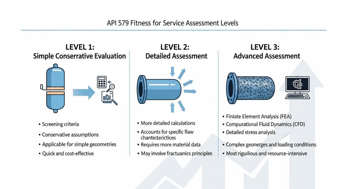
When we evaluate damaged equipment, we must follow a systematic approach that matches the complexity of the flaw with the sophistication of our analysis. The API 579-1/ASME FFS-1 standard organizes this process into three distinct levels of assessment. Each level represents a trade-off between the amount of data required, the expertise of the analyst, and the level of conservatism built into the results.
The Three Levels of Assessment Explained
Level 1 Assessment: This is the most conservative approach. It is designed to be performed by plant inspectors or maintenance engineers using basic field data and minimum calculations. The assessment rules are highly restrictive, meaning that if a component passes Level 1, you can be absolutely certain it is safe. However, many acceptable components fail Level 1 due to its inherent conservatism.
Level 2 Assessment: When a component fails Level 1, we progress to Level 2. This level requires more detailed field data and is performed by a qualified piping or pressure vessel engineer. The calculations are more complex, often involving localized stress analysis and the use of specific stress concentration factors. Level 2 reduces the conservatism of Level 1, frequently qualifying equipment that failed the initial screening.
Level 3 Assessment: This is the most advanced level of evaluation, reserved for complex geometries, severe damage, or cyclic loading conditions. It requires specialized expertise in finite element analysis (FEA) and fracture mechanics. Level 3 assessments are highly detailed and eliminate almost all unnecessary conservatism, but they require significant time, computational power, and engineering expertise.
Field Warning: Avoid Level 1 for Cyclic Service
Never apply Level 1 assessment rules to components subjected to cyclic loading or thermal shock. Level 1 rules assume static loading and elastic behavior; ignoring fatigue can lead to catastrophic, unpredicted brittle fracture. Always escalate to a Level 2 or Level 3 fatigue analysis when cyclic conditions are present.
The Math Behind the Remaining Strength Factor (RSF)
The core metric of any FFS assessment is the Remaining Strength Factor (RSF). The RSF is a ratio that compares the plastic collapse load of the damaged structure to the plastic collapse load of the undamaged, nominal structure:
Where:
• L_damaged is the plastic collapse load of the component containing the flaw.
• L_undamaged is the plastic collapse load of the component in its original, pristine condition.
According to API 579, the standard allowable remaining strength factor (RSF_a) is typically set to 0.90 for pressure vessels and piping systems. If your calculated RSF is greater than or equal to RSF_a, the component is safe for continued operation at its original Maximum Allowable Working Pressure (MAWP).
If the calculated RSF is less than RSF_a, you must either repair the component or calculate a reduced maximum allowable working pressure (MAWP_r) using the following relationship:
This formula allows us to safely “derate” the system, keeping the plant online at a lower operating pressure until the next scheduled turnaround when a permanent repair can be executed.
API 579 Assessment Levels Compared
To help you quickly determine which assessment level is appropriate for your specific engineering challenge, I have compiled this comparison matrix based on my field experience and the guidelines in ASME Codes.
| Parameter | Level 1 Assessment | Level 2 Assessment | Level 3 Assessment |
|---|---|---|---|
| Required Expertise | Plant Inspector / Maintenance Engineer | Piping / Pressure Vessel Engineer | FFS Specialist / FEA Expert |
| Data Requirements | Minimum (Basic dimensions, UT thickness) | Moderate (Detailed flaw profiles, material data) | High (Material chemistry, stress history, FEA mesh) |
| Level of Conservatism | Very High (Safe but restrictive) | Moderate (Balanced safety margins) | Low (Realistic structural behavior) |
| Typical Tools Used | Hand calculations, lookup tables | Spreadsheets, analytical software | Finite Element Analysis (FEA) software |
Technical Mapping & Specifications Matrix
This matrix maps the core technical entities, structural acronyms, and physical parameters used during an FFS evaluation, complete with their corresponding standard references.
| Entity / Acronym | Physical Parameter | Standard Reference | Application Notes |
|---|---|---|---|
| RSF | Remaining Strength Factor | API 579 Part 2 | Determines if component can run at original MAWP. |
| MAWP_r | Reduced Maximum Allowable Working Pressure | API 579 Part 2 / ASME Sec VIII | Used to derate equipment when RSF is below allowable limits. |
| LTA | Local Thin Area | API 579 Part 5 | Evaluates localized corrosion and blend-ground areas. |
| FAD | Failure Assessment Diagram | API 579 Part 9 | Used for evaluating crack-like flaws under fracture mechanics. |
Field Data Collection Checklist
Before you begin any calculations in your office, you must ensure that the data coming from the field is accurate and complete. An FFS assessment is only as good as the input parameters. Use this checklist during your next site walkdown to ensure nothing is missed.
Mandatory FFS Field Verification Steps
-
Verify Original Design Code: Locate the vessel nameplate or piping line list to confirm the original construction code (e.g., ASME Section VIII Division 1 or ASME B31.3).
-
Confirm Material Specifications: Cross-reference the original Mill Test Reports (MTRs) to verify yield strength, tensile strength, and material grade (e.g., ASTM A516 Grade 70).
-
Map the Flaw Profile: Perform high-resolution Ultrasonic Testing (UT) grid scans to map the exact length, width, and depth profile of the localized thin area (LTA).
-
Document Operating History: Review plant DCS records to identify any historical pressure or temperature excursions that exceed design limits.
-
Inspect for Environmental Cracking: Perform Wet Fluorescent Magnetic Particle Testing (WFMT) or Dye Penetrant Testing (PT) to ensure no environmental cracking is associated with the corrosion.
Field Case Study: Real-World Application
The Problem: Localized Corrosion on a High-Pressure Separator
During a scheduled turnaround at a major gas processing facility, inspectors discovered a localized thin area (LTA) on the bottom head of a high-pressure separator vessel. The vessel was designed to ASME Section VIII Division 1 with a nominal wall thickness of 18.0 mm and a design pressure of 45.0 bar. UT scans revealed that localized corrosion had reduced the wall thickness to a minimum of 12.0 mm over an area of approximately 150 mm by 120 mm. The plant manager faced a tough decision: perform an immediate weld overlay repair (requiring a 3-week shutdown costing 2.4 million) or find an engineering justification to keep the vessel online.
The Outcome: Level 2 Assessment Saves the Day
I was called in to perform a Level 2 assessment per API 579 Part 5 (Local Thin Areas). We mapped the exact corrosion profile using a 10mm by 10mm UT grid. By calculating the longitudinal and circumferential extent of the thin area, we determined the Remaining Strength Factor (RSF). The calculated RSF was 0.92, which exceeded the allowable RSF_a of 0.90. This proved that the vessel possessed sufficient structural integrity to operate safely at its original design pressure of 45.0 bar without immediate repair.
Based on this analysis, we recommended deferring the repair to the next major turnaround in 24 months. We established a temporary monitoring program using non-intrusive UT thickness measurements every 6 months to ensure the corrosion rate remained within acceptable limits. This engineering decision saved the operator 2.4 million in lost production and avoided the risks associated with field weld repairs on heavy-wall vessels.
Frequently Asked Engineering Questions
Steps in API 579 Fitness for Service
To help you navigate the complexities of the API 579-1/ASME FFS-1 standard, I have compiled answers to the most common questions I receive from field engineers and plant managers.
What is the difference between API 579 and ASME FFS-1?
Can I perform a Level 1 assessment myself?
What is the Remaining Strength Factor (RSF)?
How does API 579 handle crack-like flaws?
What happens if a component fails a Level 3 assessment?
How often should FFS assessments be re-evaluated?
===FAQ_BLOCK===
Complete Course on
Piping Engineering
Check Now
Key Features
- 125+ Hours Content
- 500+ Recorded Lectures
- 20+ Years Exp.
- Lifetime Access
Coverage
- Codes & Standards
- Layouts & Design
- Material Eng.
- Stress Analysis

📚 Recommended Resources: API 579 Fitness for Service
Read these Guides
Related posts:
![3D CAD render of a bolted flange joint assembly showing a compressed gasket.]()
Understanding Gasket m and y Factors in Flange Design
![PASS/START-PROF 4.86 pipe stress analysis software interface displaying a 3D piping model.]()
PASS/START-PROF 4.86 Released: Discover the New Pipe Stress Analysis Capabilities
![ASME certification mark stamped on an industrial pressure vessel nameplate]()
What is ASME Certification? Procedure and Mark Explained
![Professional technician inserting a high-pressure hydro jetting nozzle into a sewer pipe cleanout.]()
What is Hydro Jetting and How Does It Work?
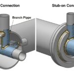
![Side-by-side comparison diagram of stub-in and stub-on piping branch connections.]()
Stub-in vs Stub-on Piping Connections: Engineering Design Guide
![A restriction orifice plate installed between pipe flanges in an industrial piping system.]()
What is a Restriction Orifice? Working, Types, and Sizing Guide