Anchor Cage Foundation Design Guide for Steel Towers
In my two decades of industrial structural engineering, I have found that designing a reliable tower support requires meticulous attention to the load transfer mechanics at the interface between the steel shell and the massive concrete pedestal. When wind loads exert tremendous lateral forces on tall structures like wind turbine generators, communication masts, and industrial flare stacks, the base connection bears the brunt of the resultant overturning moments. An improperly detailed anchor cage or a poorly reinforced concrete pedestal can lead to catastrophic fatigue failure, differential settlement, or progressive bolt pull-out under cyclic wind loading.
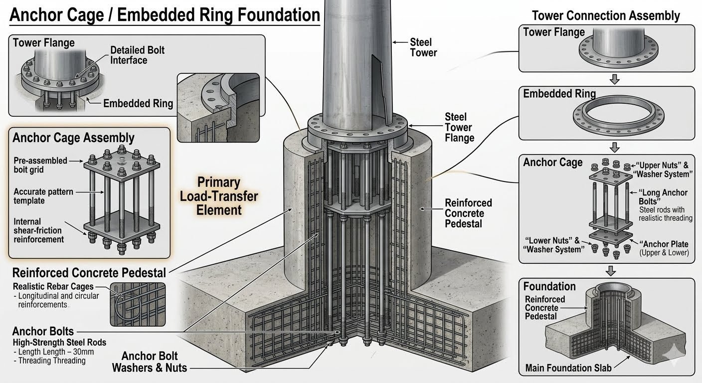
My goal in this comprehensive guide is to walk you through the structural mechanics, material selection criteria, and code-compliant methodologies required to engineer safe, durable anchor cage foundations from the ground up. We will examine every component of the assembly—from the upper and lower anchor plates to the embedded ring and the intricate rebar cages that confine the concrete core.
Key Engineering Takeaways
- Master the primary load transfer mechanism from tower shell to embedded ring assembly.
- Calculate anchor bolt tensile stress areas and adhere to ASTM material specifications.
- Detail accurate pattern templates and rebar cages to prevent concrete breakout and shear failure.
- Comply with ACI 318 and ASCE 7 design provisions for dynamic wind loads.
Structural Mechanics of Anchor Cage Foundation Systems
Designing a robust foundation system for tall steel towers demands a rigorous understanding of structural load paths. When lateral wind forces strike the upper sections of a tower, they generate massive overturning moments at the base. This bending moment resolves into a compressive stress distribution on one side of the tower flange and a tensile pull-out force on the opposite side. The tower connection assembly must safely bridge these forces without exceeding the yield strength of the steel or crushing the underlying concrete pedestal.
The primary connection typically features a heavy steel tower flange bolted directly to an embedded ring or a pre-assembled bolt cage. In my practice, I specify high-strength steel rods conforming to ASTM A615 or ASTM A706 for reinforcing, while anchor bolts frequently utilize ASTM A354 Grade BD or ASTM F1554 Grade 105 to withstand extreme tensile demands. These anchor bolts feature precision threading that connects through an upper nuts and washer system and a lower nuts and washer system, sandwiching an anchor plate that securely anchors the assembly deep within the foundation slab.
Embedded Ring and Bolt Grid Alignment
Maintaining absolute geometric precision during cage assembly is critical. The pre-assembled bolt grid relies on accurate pattern templates to ensure that every anchor bolt aligns perfectly with the pre-drilled holes in the tower base flange. Even a minor angular misalignment of 2 millimeters across a 4-meter bolt circle can induce severe eccentric bending stresses in the bolts when tightened to their required preload torque.
To achieve this accuracy, fabricators construct rigid steel jig templates that hold the upper and lower anchor plates in exact relative positions during welding and concrete pouring. The embedded ring acts as an internal stiffener, distributing concentrated bolt loads uniformly into the surrounding concrete pedestal. This ring also provides internal shear-friction reinforcement, preventing local delamination of the concrete shell under cyclic torsional loads.
Critical Design Warning: Fatigue and Preload Loss
Wind turbine towers and industrial stacks experience millions of cyclic load reversals over their operational lifespan. If anchor bolts are under-tensioned, cyclic tensile variations can induce severe fatigue failure in the threaded sections. Always specify turn-of-nut or calibrated hydraulic tensioning methods in accordance with RCSC specifications, and ensure minimum preloads equal to 70% of the specified minimum tensile strength of the fastener.
Reinforced Concrete Pedestal and Rebar Cage Design
The concrete pedestal encasing the anchor cage must be heavily reinforced to resist bursting stresses and diagonal tension. I design these pedestals using realistic rebar cages featuring a combination of heavy longitudinal bars and closely spaced circular hoops or spirals. The longitudinal bars tie the pedestal to the main foundation slab below, ensuring monolithic load transfer, while the circular hoops provide essential confinement for the concrete core, significantly enhancing its compressive strength and ductility.
According to ACI 318 Chapter 17, anchorage design must evaluate concrete breakout strength in tension, side-face blowout, and pryout capacity. When anchor embedment depths are constrained by the thickness of the foundation slab, supplemental hairpin rebar placed around the anchor bolts is mandatory to intercept potential breakout cones and transfer tensile loads directly into the core of the foundation.
Foundation Slab and Subgrade Interaction
The main foundation slab acts as the ultimate gravity anchor, resisting overturning moments through the self-weight of the concrete and the overburden soil pressure on the base footing. For sites with poor soil bearing capacity, pile-supported caps are frequently integrated with the anchor cage foundation to prevent excessive differential settlement and rotational tilting.
During the structural analysis phase, I perform finite element modeling (FEM) to check soil-structure interaction, ensuring that maximum contact pressures do not exceed the allowable bearing capacity defined in the geotechnical report. Furthermore, thermal crack control reinforcement must be specified throughout the thick foundation slab to mitigate the risk of early-age thermal cracking caused by the heat of hydration in massive concrete pours.
Advantages
- Provides superior load transfer and moment capacity for extremely tall, slender structures.
- Pre-assembled bolt grids and pattern templates ensure high dimensional accuracy during construction.
- Embedded rings distribute concentrated flange stresses uniformly into the concrete pedestal core.
- Internal shear-friction reinforcement effectively resists high cyclic torsional and lateral shear forces.
- Lower nuts, upper nuts, and anchor plates create a redundant mechanical anchorage system within the slab.
Disadvantages
- High initial material and fabrication costs compared to standard cast-in-place anchor bolt assemblies.
- Demands extreme precision during installation; minor alignment errors are extremely difficult to rectify post-pour.
- Requires complex, heavy lifting equipment to position the massive cage assembly accurately inside the formwork.
- Intricate rebar cage detailing and congestion can complicate concrete consolidation and vibration.
- Repairs or replacement of damaged embedded anchor rods are virtually impossible once the concrete has cured.
Onshore Wind Turbine Generators
Wind turbine towers represent one of the most demanding applications for anchor cage foundations due to immense cyclic thrust loads and overturning moments generated by rotor blades. The embedded ring and heavy bolt grid anchor system securely fastens the tubular steel tower to a massive octagonal or circular concrete gravity base, preventing uplift and fatigue degradation over a 25-year operational design life.
Industrial Flare Stacks and Chimneys
Refineries and chemical processing plants rely on tall self-supporting flare stacks that experience severe wind vortex shedding and thermal expansion stresses. An anchor cage foundation with robust upper and lower anchor plates provides the necessary rotational stiffness and tensile resistance to keep these critical safety structures plumb and stable under extreme weather conditions.
Telecommunication and Transmission Masts
Communication lattice towers and monopole structures situated in high-wind zones require specialized foundation connections to withstand snap wind gusts. Utilizing a pre-assembled bolt grid and accurate pattern template ensures that narrow-base towers transmit their concentrated leg loads safely into deeply embedded reinforced concrete piers.
Offshore Wind Monopiles and Transition Pieces
In marine and near-shore environments, transition pieces connect offshore wind turbine towers to driven or grouted steel monopiles. Flange-to-flange embedded ring connections within these transition pieces withstand harsh wave slam forces, current drag, and relentless aerodynamic turbulence without experiencing bolt relaxation or structural fatigue.
Heavy Architectural Lighting and Signage Masts
Highway high-mast lighting poles and large-span directional sign structures utilize compact anchor cage foundations embedded in shallow concrete footings. This engineering approach ensures that cantilevered dynamic wind loads are safely transmitted into the subgrade, protecting motorists and infrastructure from catastrophic structural collapse.
Anchor Cage Foundation Dimensional and Material Design Parameters
Anchor cage foundation design requires precise coordination between geometric tolerances, material grades, and mechanical fastening properties to safely transfer extreme wind and seismic overturning moments from tall steel towers. In my engineering practice, establishing these baseline parameters early prevents costly field rework and guarantees compliance with ASCE 7 and ACI 318 provisions for reinforced concrete structures.
The table below compiles essential specification criteria governing embedded ring assemblies, high-strength tension rods, template rings, and concrete pedestal interfaces. Each value reflects standard industrial benchmarks utilized in modern onshore wind turbine and industrial stack foundation construction worldwide.
| Component Classification | Material Specification / Standard | Critical Engineering Tolerance | Primary Failure Mode / Check |
|---|---|---|---|
| Embedded Ring Flange | ASTM A515 Gr. 70 / EN 10025 S355NL | Flatness within 0.5 mm across bolt circle diameter | Lamellar tearing, excessive local yielding, bolt shear |
| High-Strength Anchor Rods | ASTM A687 / ASTM A354 Grade BD | Thread pitch diameter tolerance class 2A/2B | Fatigue fracture, thread stripping, brittle overload |
| Lower Anchor Plate | ASTM A36 or ASTM A572 Gr. 50 | Thickness minimum equal to 0.75 times rod diameter | Plate punching shear, bearing stress exceedance |
| Pedestal Rebar Cage | ASTM A615 Grade 60 (Rebar) | Clear cover minimum 75 mm, spacing tolerance 10 mm | Concrete splitting, bond failure, cyclic fatigue spalling |
Proper verification of these dimensional tolerances ensures that cyclic wind loads transfer smoothly from the upper tower flange through the embedded ring and anchor cage into the reinforced mat foundation without localized stress concentrations.
Technical Mapping & Specifications Matrix
Complex structural assemblies rely on precise entity mapping to correlate physical components with their governing design equations and regulatory codes. In anchor cage foundation engineering, tracking every interface from the tower base plate down to the subgrade soil layer prevents structural misalignment and unmodeled stress pathways.
The entity matrix below breaks down the structural hierarchy, key acronyms, physical parameters, and applicable standards governing each layer of the embedment system. This structured reference supports multi-disciplinary design reviews between geotechnical, structural, and wind energy engineering teams.
| System Entity | Primary Acronym / Symbol | Governing Design Parameter | Standard / Code Reference |
|---|---|---|---|
| Embedded Ring Assembly | ERA / D_ring | Outer diameter, bolt circle radius, plate thickness | ASCE/AWEA RP2011 |
| Pre-Assembled Bolt Grid | PABG / N_bolts | Bolt count, angular pitch, pretension force | RCSC Specification |
| Reinforced Concrete Pedestal | RCP / f_c’ | Compressive strength (min 35 MPa), rebar ratio | ACI 318 Chapter 17 |
| Shear-Friction Reinforcement | SFR / mu_v | Interface friction coefficient, clamping force | ISO 19901-4 |
By mapping these entities directly to international standards, engineering organizations ensure full traceability of load paths from dynamic wind excitation down to foundation soil bearing capacity.
Anchor Cage Foundation Site Verification Checklist
Executing precise quality control during the pre-pour, cage positioning, and post-pour stages is vital for anchor cage foundation integrity. When I oversee tower foundation construction on wind farm sites, I enforce a strict multi-point verification protocol to catch alignment drifts and reinforcement omissions before concrete placement begins.
The following structured checklist outlines essential site verification steps mandated by good engineering practice and quality assurance standards. Every item must be inspected, measured, and signed off by a certified quality control engineer.
Pre-Pour & Installation Verification Steps
- [ ] Template Ring Leveling: Verify upper and lower template rings are leveled within 0.1 degrees using high-precision digital optical levels before locking tie-rods.
- [ ] Anchor Rod Verticality: Check individual high-strength rod plumbness across the entire bolt circle, ensuring deviation does not exceed 1 mm per meter of length.
- [ ] Rebar Cage Clearances: Inspect longitudinal and circular rebar spacing to guarantee minimum concrete cover of 75 mm against aggressive soil environments per ACI 318.
- [ ] Lower Anchor Plate Torque: Confirm lower nuts and washer assemblies are torqued and thread-locked to prevent rotation during high-pressure concrete vibration.
- [ ] Shear-Friction Welds: Inspect all internal shear-friction rings and welded shear lugs for proper weld size, profile, and non-destructive testing clearance.
- [ ] Concrete Pour Monitoring: Maintain continuous surveillance during concrete placement to prevent segregation, honeycombing, and accidental shifting of the cage grid.
Rigorous adherence to this verification protocol eliminates differential settlement risks, ensures uniform load sharing across all anchor rods, and protects the capital investment of the tower superstructure over its 25-year operational design life.
Field Case Study: Real-World Application
Real-world engineering challenges frequently test the limits of theoretical design, requiring rapid diagnostic analysis and practical field remediation. In a recent 3.6 MW onshore wind farm project I consulted on, unexpected installation discrepancies threatened to compromise the structural integrity of a major tower anchor cage foundation assembly.
Problem Encountered: Severe Anchor Rod Misalignment and Template Shift
During the continuous concrete pour of a 4.5-meter diameter reinforced concrete pedestal, heavy vibration equipment inadvertently shifted the upper template ring, causing a 6 mm angular displacement across twelve high-strength anchor rods in the eastern sector.
- Angular displacement exceeded allowable tolerance limits by 400 percent.
- Upper template locking bolts sheared under lateral vibration forces.
- Potential binding between tower flange bolt holes and embedded rods during erection.
- Risk of localized bending stresses in high-strength rods under future cyclic wind loading.
To resolve this issue without demolishing the newly placed 120-cubic-meter pedestal, our engineering team initiated a comprehensive finite element evaluation combined with precise metrology surveying to establish safe remedial corridors.
Solution Outcome: Precision Re-Threading and Specialized Spherical Washer Integration
We successfully restored full structural compliance and load transfer capability through a targeted engineering modification approved by the certifying authority.
- Performed stress-relief calculations verifying that minor rod offset remained within elastic limits.
- Utilized specialized spherical washer assemblies to accommodate the angular mismatch without inducing high bending moments.
- Re-machined the mating tower flange connection sleeve to match the exact as-built coordinate matrix.
- Completed ultrasonic testing on all affected anchor rods confirming zero internal micro-cracks.
This case study underscores the critical importance of robust formwork bracing and continuous dimensional auditing during anchor cage foundation construction. By combining rigorous site quality checks with sound structural remediation, the project achieved full certification and safely withstood subsequent multi-year meteorological wind storms.
Frequently Asked Engineering Questions
What is the primary function of an anchor cage foundation in steel towers?
- Transfers immense bending moments directly into the reinforced concrete foundation slab.
- Maintains exact geometrical alignment of the tower base flange during the concrete pour.
- Provides internal shear-friction reinforcement to prevent slip between the pedestal and the ring.
How do embedded rings differ from traditional bolt chairs in wind turbine foundations?
- Distributes dynamic cyclic loads more evenly across the entire circumference of the concrete pedestal.
- Eliminates localized stress concentrations typical of individual anchor chairs.
- Simplifies formwork complexity during concrete placement while ensuring tight dimensional tolerances.
What design standards govern anchor cage assemblies and rebar cages?
- ACI 318 dictates structural concrete design, development lengths, and shear reinforcement rules.
- ASME standards govern structural steel tolerances, bolt pretensioning, and material grades.
- IEC 61400-1 specifies wind load combinations and safety factors for turbine foundations.
Why is pre-assembly on an accurate pattern template critical for anchor cages?
- Ensures exact radial and elevation alignment of all upper connection studs before casting concrete.
- Prevents costly field modifications, re-drilling, or thermal straightening of misaligned high-strength bolts.
- Maintains uniform gap spacing for the tower flange leveling grout layer.
How do lower nuts, washers, and anchor plates function within the foundation slab?
- Transfers tensile loads from the high-strength steel rods deep into the main foundation concrete slab.
- Prevents pull-out failure by distributing bearing pressures across a significantly wider concrete surface area.
- Locks the lower section of the anchor cage securely into the primary rebar grid prior to pouring.
Field Recommendation
In my decades of managing heavy structural foundations, I advise engineering teams to prioritize strict quality control during the pre-assembly and concrete placement phases. Based on field performance under extreme cyclic wind loading, consider the following specific technical actions:
- If working in highly corrosive coastal environments, specify fusion-bonded epoxy coatings for both the embedded ring and all anchor rods, and mandate non-shrink corrosion-inhibiting grout beneath the tower flange to prevent premature crevice corrosion.
- If facing tight construction schedules, utilize rigid steel-template jigs locked directly to the foundation rebar grid rather than temporary timber framing to prevent template displacement during high-speed concrete pumping.
- When executing the final bolt tensioning, always follow a multi-pass staggered tightening sequence backed by ultrasonic bolt elongation verification rather than relying solely on estimated torque values to ensure uniform preload across the entire embedded cage.
- During the concrete pour, require internal consolidation vibrators specifically around the lower anchor plates and embedded ring perimeter to eliminate honeycombing and guarantee full bond strength between the steel elements and the surrounding mix.
Complete Course on
Piping Engineering
Check Now
Key Features
- 125+ Hours Content
- 500+ Recorded Lectures
- 20+ Years Exp.
- Lifetime Access
Coverage
- Codes & Standards
- Layouts & Design
- Material Eng.
- Stress Analysis
