Anchor Bolt Pretension Mechanics for Tower Flange Foundation Connections
Anchor bolt pretension: The controlled application of initial tensile stress to structural fasteners in tower-to-foundation connections, complying with ASME PCC-1 and AISC specifications to eliminate interface gaps and prevent fatigue failure under cyclic wind loads.
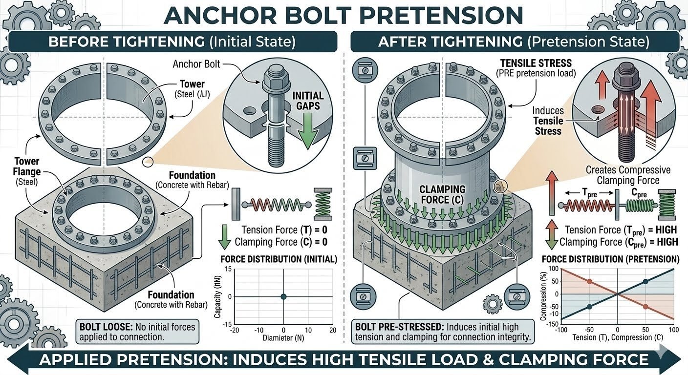
In my two decades of reviewing heavy structural foundations and tower flange connections, I have seen premature joint failures traced back to a fundamental misunderstanding of initial pretension mechanics. Before tightening, an un-tensioned anchor bolt experiences zero tensile stress and zero clamping force, leaving micro-gaps between the steel base flange and the high-strength concrete foundation. These initial gaps compromise the entire load path, exposing the assembly to severe bending moments and resonant vibration during operation.
When we apply the correct anchor bolt pretension, the physical state of the joint transforms entirely. The bolt stretches within its elastic limit, generating a massive tensile preload that translates directly into high compressive clamping force across the flange-to-foundation interface. This mechanical clamping eliminates joint separation, distributes cyclic fatigue stresses safely through the embedded rebar and grout pad, and maintains structural integrity against extreme wind shear.
Core Engineering Takeaways
- Initial un-tensioned states result in zero clamping force and severe cyclic fatigue vulnerability.
- Proper pretension creates an inverse force distribution where bolt tension and interface compression balance dynamically.
- Adherence to ASTM material grades and controlled torque/tension methods ensures long-term joint stability.
Engineering Mechanics of Anchor Bolt Pretension and Joint Behavior
Pretension mechanics and load transfer: The fundamental operational mechanics of structural anchor bolt pretension rely on establishing a high clamping preload that exceeds external tensile separating forces, thereby shielding the fastener from destructive cyclic fatigue amplitudes.
Before tightening, the initial state of a tower flange resting on a concrete foundation is characterized by physical imperfections, surface roughness, and microscopic leveling gaps. In this un-tensioned condition, the bolt tension force T = 0 and the interface clamping force C = 0. A force distribution plot across the bolt circle diameter exhibits a flat, zero-capacity profile. Any lateral or overturning moment from wind loads immediately causes the flange to lift off the concrete, slamming back down with impact loading that shears threads and crushes grout.
Applying torque or hydraulic tension alters this behavior by elongating the bolt shank according to Hooke’s Law. The induced bolt tension T_pre creates an equal and opposite compressive clamping force C_pre at the flange-to-foundation interface. This forces complete closure of initial gaps, establishing uniform contact pressure across the annular bearing area. The force distribution plot in this tightened state reveals an inverse relationship: as external overturning moments increase tension on the windward side, compression decreases proportionally on that sector while remaining securely clamped on the leeward side.
Mathematical Formulation of Bolt Elongation and Clamping
To calculate the required torque (T_q) and resulting preload (F_p), piping and structural engineers use the standard friction-compensated formula defined in ASME PCC-1:
T_q = K * d * F_p
- T_q: Applied tightening torque (Newton-meters or foot-pounds).
- K: Nut factor or dimensionless torque coefficient (typically 0.12 to 0.15 for lubricated heavy hex structural bolts).
- d: Nominal bolt diameter (millimeters or inches).
- F_p: Target bolt preload, usually specified as 70% to 75% of the specified minimum tensile strength (SMTS) per ASTM A325 or ASTM A490 standards.
Critical Field Warning: Over-Tensioning and Yielding Risks
Exceeding 80% of the bolt material yield strength during tensioning can cause permanent plastic deformation, necking, and sudden brittle fracture under operational wind shear. Always verify calibration certificates of hydraulic tensioners and torque wrenches prior to executing bolt-up sequences.
Managing relaxation and elastic interaction is equally important during multi-bolt tightening sequences. As subsequent bolts in a circular tower flange pattern are tightened, the elastic compression of the flange and concrete foundation causes previously tightened adjacent bolts to lose a fraction of their initial preload. To counteract this loss, engineers mandate multi-pass tightening patterns (e.g., 30%, 60%, 100% cross-pattern sequences) followed by a final verification pass after 24 hours to account for embedment relaxation and grout creep.
Pretension trade-offs: Evaluating the operational benefits against the mechanical limitations of controlled anchor bolt pretension ensures safe, cost-effective structural foundation design.
Advantages
- Eliminates joint separation and flange lifting under severe cyclic wind moments.
- Significantly enhances fatigue life by reducing dynamic stress fluctuations in the bolt shank.
- Prevents loosening caused by low-frequency resonant vibrations from heavy rotating equipment.
- Ensures uniform load distribution across the concrete foundation and embedded rebar cage.
- Complies fully with ASME PCC-1 and AISC joint integrity requirements.
Disadvantages
- Requires specialized hydraulic tensioning equipment and calibrated electronic torque tools.
- Demands highly skilled, certified technicians to execute strict multi-pass tightening patterns.
- Prone to preload loss from embedment relaxation, gasket creep, or concrete grout settlement.
- Higher initial capital expenditure for high-strength ASTM A490 or F1554 Grade 105 fasteners.
- Risk of thread galling and stress corrosion cracking if anti-seize lubricants are misapplied.
Industry deployment sectors: Anchor bolt pretension methodologies are deployed across critical infrastructure sectors where massive dynamic overturning loads demand absolute structural reliability.
Onshore and Offshore Wind Turbine Towers
Wind turbine towers experience immense cyclic overturning moments and thrust loads from rotating blades. Proper pretension of foundation anchor bolts prevents base flange micro-separation, eliminating bolt fatigue failure and costly structural retrofits over a 25-year operational lifespan.
Process Plant Distillation Columns and Stacks
Tall vertical refinery columns and industrial flare stacks are subject to extreme seismic events and high wind shear forces. Controlled hydraulic pretensioning of skirt base anchor bolts ensures the foundation interface remains rigidly clamped without yielding the high-strength anchor studs.
High-Voltage Electrical Transmission Monopoles
Heavy-duty power transmission monopoles and substation support structures rely on pre-loaded anchor bolt assemblies to resist torsional twisting and severe ice-loading conditions. Consistent clamping force prevents structural looseness and progressive foundation degradation.
Heavy Rotary Kilns and Industrial Dryers
Industrial rotary kilns operating in cement and mineral processing plants generate high-frequency vibrations and thermal expansion stresses. Pretensioned foundation anchoring maintains precise machinery alignment and prevents baseplate shifting under continuous heavy rotation.
