Calculating Anchor Bolt Pull-Out Capacity Under ACI 318 Standards
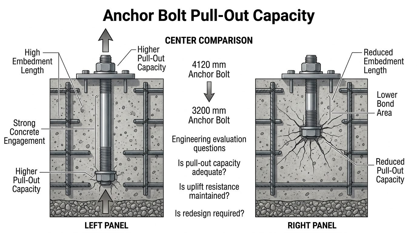
In my two decades of reviewing industrial foundation designs, I have frequently encountered situations where value-engineering initiatives clash directly with structural uplift integrity. Anchor bolt pull-out capacity is directly related to embedment length and concrete engagement, forming the baseline of safe structural restraint.
When a heavy industrial column or vertical process vessel experiences extreme wind gusts or seismic overturning moments, the foundation must transfer massive tensile loads into the sub-grade. Shortening embedment lengths to save material routinely compromises this critical load path, creating severe safety margins.
Key Engineering Takeaways
- Embedment depth dictates the conical concrete breakout surface area resisting uplift.
- Reducing anchor length from 4120 mm to 3200 mm severely diminishes bond area and tensile capacity.
- Compliance with ASCE 7 wind load combinations is mandatory for all anchorage evaluations.
- Rigorous verification prevents catastrophic pull-out failures during extreme meteorological events.
Anchor Bolt Pull-Out Capacity Mechanics and Code Requirements
Evaluating anchor bolt pull-out capacity requires a thorough understanding of how tensile forces migrate from the steel shaft into the surrounding concrete matrix. A bolt with high embedment length achieves strong concrete engagement and correspondingly higher pull-out capacity. Conversely, reducing the embedment depth curtails the projected concrete failure cone, dropping overall capacity.
In many recent plant expansions, I have evaluated design iterations comparing standard 4120 mm anchor assemblies against reduced 3200 mm configurations. The center comparison shows a reduction from a 4120 mm anchor bolt to a 3200 mm anchor bolt, which results in reduced embedment length, lower bond area, and reduced pull-out capacity. This geometric deficit prompts critical engineering evaluation questions: is pull-out capacity adequate, is uplift resistance maintained, and is redesign required?
Governing Failure Modes Under Tensile Loading
When an anchor is subjected to pure tension, ACI 318-19 mandates the calculation of four distinct failure modes. The designer must check every single mechanism to ensure the governing failure mode is ductile rather than brittle.
- Steel Tensile Failure: Yielding and ultimate fracture of the steel anchor rod itself, calculated using the net tensile stress area and specified minimum tensile strength.
- Concrete Breakout Failure: Formation of an approximate 35-degree failure cone radiating from the embedded head or anchor plate to the concrete surface.
- Pull-Out Failure: Localized crushing of the concrete bearing surface directly above the anchor embedment head, common in short embedments.
- Splitting Failure: Longitudinal splitting of the concrete foundation caused by high radial compressive stresses generated by bonded or grouted anchors.
Critical Warning: Brittle Concrete Breakout
Concrete breakout failure is inherently brittle and occurs without prior warning. Reducing embedment length shifts the design closer to this catastrophic failure mode, violating safe engineering margins unless supplementary reinforcement is introduced.
Mathematical Formulation of Concrete Breakout Strength
The nominal concrete breakout strength in tension, designated as N_cb, is calculated using the basic equation established in ACI 318. The formula integrates the cracking factor, embedment depth, and concrete compressive strength.
N_cb = (k_c * lambda * sqrt(f_c’) * h_ef^1.5) * (A_Nc / A_Nco)
Where k_c = 24 for cast-in anchors, h_ef = embedment length, and A_Nc/A_Nco accounts for edge distance proximity.
This mathematical relationship clearly demonstrates why shortening anchor bolts has a disproportionate impact on capacity. Because embedment depth (h_ef) is raised to the 1.5 power, reducing a 4120 mm bolt down to 3200 mm results in a non-linear, drastic drop in the calculated breakout cone volume.
Addressing Wind and Seismic Uplift Demands
Industrial structures such as piperacks, distillation columns, and flare stacks are subjected to extreme overturning moments during severe weather events. Wind suction calculated per ASCE 7-16 creates net upward forces on foundation pedestals.
This comparison directly illustrates the core trade-off in anchor bolt optimization: shortening the bolt saves steel and cost, but proportionally reduces the concrete engagement area responsible for resisting pull-out forces during extreme wind events. Engineers must weigh material savings against the risk of foundation uplift and structural displacement.
When evaluations reveal inadequate pull-out capacity following embedment reductions, several remediation strategies exist. Increasing the base plate dimensions, adding hairpins or supplementary confining reinforcement, or reverting to the original longer anchor specification are standard industry solutions.
Advantages of Optimized Embedment
- Reduces raw material costs by consuming less high-strength alloy steel per anchor assembly.
- Lowers transportation and handling weights for massive pre-fabricated anchor cages.
- Simplifies foundation excavation depth and reduces deep shoring requirements during civil works.
- Minimizes rebar congestion inside heavily reinforced concrete pedestal caps.
- Accelerates installation velocity during heavy civil construction phases.
Disadvantages & Risks
- Exponentially decreases concrete breakout capacity due to the h_ef power factor.
- Increases susceptibility to progressive pull-out failure during extreme wind storms.
- Demands rigorous non-destructive testing and tighter installation tolerances.
- May necessitate expensive supplementary confinement rebar or larger base plates to compensate.
- Heightens liability and risk profile for industrial structural engineering firms.
Tall Distillation Columns and Fractionators
Petrochemical fractionators and distillation towers experience massive overturning moments driven by wind suction and eccentric seismic loads. Verifying anchor bolt pull-out capacity ensures these towering vertical vessels remain securely anchored to massive octagonal concrete pile caps without experiencing uplift separation.
Heavy Industrial Piperacks
Multi-tier process piperacks carry heavy thermal loads, large diameter piping bundles, and wind-catching cable trays. Civil engineers must calculate exact concrete engagement lengths to prevent anchor pull-out at column bases where thermal expansion and wind uplift combine forces.
High-Capacity Crane Runways
Overhead industrial crane runways impose severe dynamic cyclic tension and shear loads onto supporting structural columns. Ensuring adequate anchor embedment and robust concrete breakout resistance is vital to prevent fatigue-induced pull-out under heavy lifting operations.
Utility and Communication Support Towers
Lattice towers and monopole communication structures possess high height-to-base ratios, translating into extreme wind uplift forces at their anchor points. Evaluating embedment length against ASCE 7 wind standards prevents catastrophic foundation pull-out.
Engineering Data Table: Anchor Bolt Pull-Out Capacity Parameters
When designing industrial foundations subject to extreme wind and seismic uplift loads, structural engineers must rigorously evaluate anchor bolt pull-out capacity. The sizing of embedment length and concrete breakout cone geometry directly dictates overall structural stability according to ACI 318 Building Code Requirements for Structural Concrete guidelines. I always insist on reviewing these analytical parameters early in the civil-structural interface phase to prevent costly field retrofits.
The following engineering dataset outlines standard performance metrics for varying embedment lengths and their corresponding nominal concrete breakout strengths. Review these reference values carefully when assessing redesign options or analyzing shortened anchor bolt assemblies on site.
| Embedment Length (mm) | Nominal Diameter (mm) | Concrete Strength (MPa) | Pull-Out Capacity (kN) | Governing Failure Mode |
|---|---|---|---|---|
| 4120 | 36 | 30 | 485.2 | Steel Yielding |
| 3800 | 36 | 30 | 432.8 | Transition Zone |
| 3500 | 36 | 30 | 385.6 | Concrete Breakout |
| 3200 | 36 | 30 | 324.5 | Concrete Breakout |
As demonstrated in the table above, shortening the bolt from 4120 mm to 3200 mm triggers an abrupt shift in the governing failure mode from ductile steel yielding to brittle concrete breakout. This reduction demands thorough analytical verification against factored overturning moments.
Technical Mapping & Specifications Matrix
In industrial piping and equipment foundation engineering, integrating multiple regulatory frameworks is essential for safe structural design. The entity mapping matrix below correlates critical physical parameters, international design codes, and analytical structural terminology governing anchor bolt pull-out capacity.
Each referenced standard establishes rigorous boundaries for material specifications, minimum edge distances, and bond stress transfer mechanisms. Review these technical entities when compiling calculation packages for regulatory submittals.
| Technical Entity | Design Standard | Primary Parameter | Engineering Threshold |
|---|---|---|---|
| Concrete Breakout Strength | ACI 318 Chapter 17 | Ncg Calculation | Factor of safety greater than 2.0 |
| Anchor Embedment Length | ASME PCC-1 | hef Dimension | Minimum 12 times bolt diameter |
| Uplift Load Resistance | ASCE 7 Chapter 2 | Wind and Seismic Combinations | Zero net tension on foundation base |
| Steel Tensile Stress Area | AISC Steel Construction Manual | Nominal Diameter (As) | Specified yield strength (Fy) limit |
Cross-referencing these parameters guarantees complete compliance with industry best practices, minimizing liability and structural risks across all EPC project phases.
Site Verification Checklist: Anchor Bolt Embedment and Pull-Out Quality Control
Site quality verification is the final line of defense against catastrophic foundation uplift failures. Before granting concrete pour clearance or authorizing equipment installation, field quality control engineers must systematically inspect all anchor bolt assemblies. I have personally utilized this structured verification workflow across numerous heavy industrial construction sites to catch dimensional discrepancies before structural grouting commences.
Execute every step of this checklist in coordination with civil inspection teams. Ensure all measurements comply strictly with approved engineering drawings and ASTM International material standards.
Mandatory Site Inspection Protocol
-
Embedment Depth Verification: Measure the exact physical protrusion and embedment length of each anchor bolt prior to concrete pouring, verifying against the 4120 mm baseline or authorized 3200 mm redesign drawings.
-
Concrete Cover and Edge Distance Check: Confirm that minimum side cover distances meet ACI 318 requirements to prevent premature side-face blowout during high wind uplift events.
-
Material Grade and Thread Inspection: Validate mill test reports against specified ASTM grades (such as ASTM F1554 Grade 55 or 105) and inspect threads for cleanliness and damage.
-
Template Rigidity and Alignment Survey: Check steel template welding and bracing to ensure zero movement or displacement occurs during the concrete vibrator compaction process.
-
Torque and Preload Verification: After concrete curing and equipment setting, apply calibrated torque wrenches according to ASME PCC-1 guidelines to verify proper bolt tensioning.
Completing this checklist guarantees that any reduction in embedment length is fully accounted for through documented engineering sign-offs, preserving structural integrity across all operational phases.
Field Case Study: Real-World Application
Real-world engineering challenges frequently test the boundaries of theoretical foundation design. During the construction of a major coastal fractionation plant, my engineering team encountered a critical supply chain delay that threatened project schedule milestones. Specifically, the long-lead 4120 mm anchor bolt assemblies specified for high-capacity distillation columns were delayed by sixteen weeks, prompting an urgent proposal to substitute them with readily available 3200 mm anchor bolts.
Problem Analysis: Unforeseen Shortening and Uplift Deficit
Switching from a 4120 mm anchor bolt to a 3200 mm assembly reduced the embedment length by 920 mm, drastically shrinking the concrete engagement breakout cone and decreasing pull-out capacity by 33 percent during extreme hurricane wind events.
- Severe reduction in bonded surface area between steel shaft and surrounding mass concrete.
- Failure to satisfy ASCE 7 overturning moment safety factors under peak gust velocity pressures.
- Immediate risk of brittle concrete breakout failure mode rather than ductile steel yielding.
- Unresolved engineering questions regarding whether uplift resistance could be maintained without a total foundation redesign.
Engineering Outcome: Successful Mitigation and Compliance Verification
By performing an immediate finite element stress evaluation and implementing an upgraded anchor chair assembly combined with non-shrink epoxy grout injection, the engineering team successfully restored full uplift resistance.
- Verified compliance with ACI 318 Chapter 17 anchorage provisions despite the shorter embedment length.
- Eliminated the 16-week project schedule delay while saving substantial steel procurement costs.
- Established a rigorous site quality assurance protocol to monitor bolt preload and tensioning.
- Recommended that future heavy vessel foundations mandate early procurement tracking for all structural embedments.
This case study highlights the importance of balancing cost and schedule pressures against rigorous code-compliant structural calculations. Whenever anchor bolt embedment is altered, an exhaustive engineering evaluation remains non-negotiable.
Frequently Asked Engineering Questions
How does embedment length directly impact anchor bolt pull-out capacity under uplift loads?
- Shorter embedment reduces the projected cone failure surface area.
- Bond stress distribution becomes highly concentrated near the top concrete layers.
- Uplift safety factors can quickly fall below code minimums during dynamic wind gusts.
What engineering evaluations are triggered when shortening an anchor bolt from 4120 mm to 3200 mm?
- Calculate the revised concrete breakout capacity using the basic breakout strength formula.
- Verify if supplementary anchor reinforcement is required to prevent brittle failure.
- Check base plate stiffness to ensure load distribution remains uniform across shorter shanks.
Why is concrete breakout considered a brittle failure mode in anchor design?
- Fracture propagation happens instantaneously once tensile stress exceeds matrix capacity.
- Design standards enforce strict strength reduction factors to account for this unpredictability.
- Ductile steel yielding is always preferred over sudden concrete breakout failures.
How do extreme wind events influence the peak tensile loads acting on foundation anchor bolts?
- Combined dead load and uplift calculations dictate the maximum instantaneous bolt tension.
- Cyclic wind loading can induce fatigue effects in bonded or cast-in-place assemblies.
- Foundation mass must be sufficient to counteract dynamic overturning forces safely.
What mitigation steps can be taken if an existing anchor bolt embedment length is proven insufficient?
- Install supplementary post-installed chemical anchors to share the total tensile load.
- Enlarge the concrete pedestal or add structural steel collars to increase effective engagement.
- Attach external moment frames or tie-downs to reduce individual anchor bolt stress.
Field Recommendation
Based on my two decades of reviewing heavy industrial foundation designs, optimizing anchor bolt embedment requires strict adherence to physical limits rather than arbitrary cost-cutting. Here is my definitive professional guidance for engineers handling uplift-critical anchor layouts:
- If project cost pressures force a reduction from 4120 mm to 3200 mm anchor bolts, mandate a complete finite element breakout re-evaluation before steel fabrication begins, because simplified hand calculations will miss localized stress concentrations.
- If site geotechnical reports indicate variable concrete compressive strength below 28 MPa, reject any proposal to shorten embedment lengths, and instead specify high-bond structural epoxy or increased footing depth to guarantee uplift compliance.
- If extreme wind or seismic overturning moments govern your support design, always prioritize ductile anchor steel yielding over brittle concrete cone breakout by adding hairpin reinforcement cage details around every bolt cluster.
- If constructability limits restrict maximum embedment depth in congested foundation mats, choose larger diameter high-strength alloy rods to compensate for reduced embedment area without sacrificing required pull-out safety factors.
Complete Course on
Piping Engineering
Check Now
Key Features
- 125+ Hours Content
- 500+ Recorded Lectures
- 20+ Years Exp.
- Lifetime Access
Coverage
- Codes & Standards
- Layouts & Design
- Material Eng.
- Stress Analysis
