Effect of Anchor Bolt Diameter on Structural Foundation Performance
In my two decades of industrial piping and structural foundation design, I have frequently observed that anchor bolt sizing is often treated as an afterthought rather than the critical load transfer mechanism it truly is. When designing massive pipe racks, heavy rotating equipment pedestals, and vertical process columns, the transition of shear and tensile loads from the structural steel baseplate into the reinforced concrete pier relies entirely on the correct selection of anchor bolt diameter.
Engineers must carefully evaluate how scaling up from a standard 36 mm (e.g., M36) assembly to an M48 or heavy-duty M64 bolt fundamentally shifts steel area sum, cost profiles, and concrete breakout limits. Throughout this analysis, I will break down the exact performance metrics that govern modern anchorage design under seismic and thermal load combinations.
Key Engineering Takeaways
- Steel Area Scaling: Increasing diameter from M36 to M64 triples the effective steel tensile area from 4,072 mm-squared to 12,868 mm-squared across standard 4-bolt clusters.
- Concrete Capacity Limits: M36 designs frequently hit lower bound concrete breakout limits, whereas M64 arrangements unlock up to 30 percent pedestal size reduction.
- Cost vs. Performance: While M64 bolts demand higher initial material and installation expenditure, their superior load bearing minimizes thermal deformation and maximizes structural efficiency.
Effect of Anchor Bolt Diameter on Structural Performance and Capacity
When designing structural anchorages for heavy industrial facilities, selecting the appropriate anchor bolt diameter dictates the entire load transfer path from the superstructure to the foundation. In my experience reviewing foundation packages for high-temperature process columns and reciprocating compressors, the transition between M36, M48, and M64 sizes involves complex trade-offs in steel area, nominal capacity, concrete breakout cones, and overall project economics.
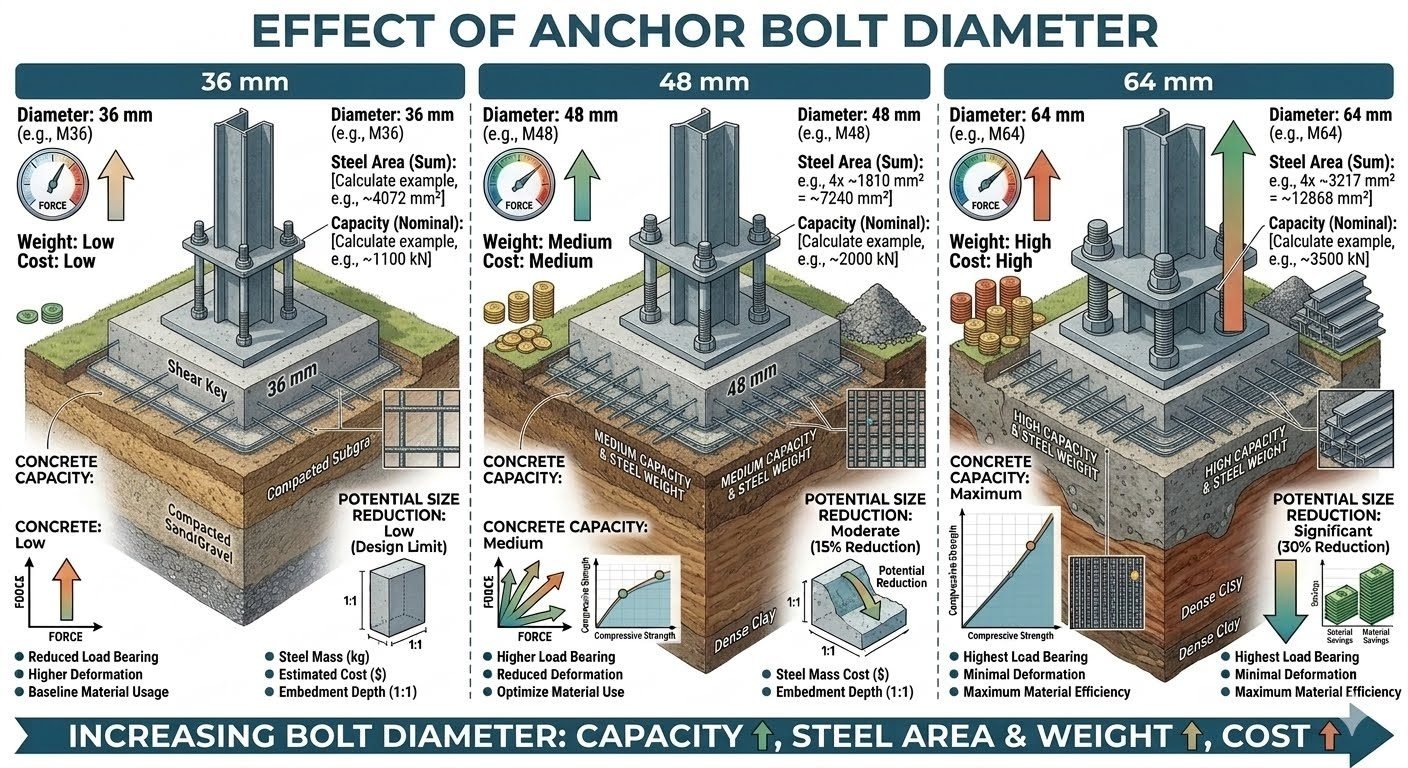
The 36 mm bolt (typically configured as M36) provides a modest steel area sum of approximately 4,072 mm-squared across a standard 4-bolt group. This configuration yields a nominal tensile capacity of roughly 1,100 kN. While suitable for smaller pipe rack columns and secondary equipment supports, the M36 bolt frequently triggers a design bottleneck where the concrete breakout capacity governs, resulting in zero potential pedestal size reduction and larger required foundation footprints.
Anchor Bolt Mechanical Property Breakdown
- M36 Diameter: Steel area sum 4,072 mm-squared, nominal capacity 1,100 kN, low weight and cost, zero concrete footprint reduction.
- M48 Diameter: Steel area sum 7,240 mm-squared, nominal capacity 2,000 kN, moderate weight and cost, 15 percent potential pedestal size reduction.
- M64 Diameter: Steel area sum 12,868 mm-squared, nominal capacity 3,500 kN, high weight and cost, maximum material efficiency with 30 percent footprint reduction.
Stepping up to a 48 mm bolt (M48) substantially alters the mechanical baseline. The steel area sum increases to approximately 7,240 mm-squared, elevating the nominal tensile capacity to 2,000 kN. This medium-weight and medium-cost option balances installation effort with structural output. In structural design calculations, the M48 configuration typically enables a moderate 15 percent potential reduction in concrete pier dimensions because the increased steel capacity distributes concentrated loads more effectively into a denser breakout cone.
Critical Design Warning: Concrete Edge Distance and Spacing
When specifying larger anchor diameters like M64, engineers must verify that the concrete pier edge distance and clear spacing between bolts satisfy ACI 318 Chapter 17 requirements. Failure to provide adequate edge distance will cause premature side-face blowout failure long before the steel tensile yield strength or full concrete breakout capacity of the M64 bolt is reached.
At the upper end of heavy industrial applications, the 64 mm bolt (M64) represents the peak of high-capacity structural anchorage. With a combined steel area of 12,868 mm-squared across a 4-bolt group, the nominal capacity surges to approximately 3,500 kN. Although M64 bolts demand heavy mechanical handling equipment during installation and carry a higher material cost premium, they deliver maximum concrete capacity, minimal thermal or mechanical deformation, and ultimate material efficiency. This high-load capability enables a significant 30 percent potential size reduction in the surrounding concrete foundations, drastically lowering excavation and bulk concrete costs on congested plot plans.
Ultimately, the design trend confirms a direct proportional relationship: increasing the anchor bolt diameter simultaneously increases structural capacity, total steel area, component weight, and procurement cost. Navigating this balance requires meticulous adherence to ASME PCC-1 guidelines for pressure boundary bolting and structural anchorage installation practices.
Advantages & Disadvantages
Advantages of Larger Diameters (M48/M64)
- Significantly higher nominal tensile capacity (up to 3,500 kN for M64 groups).
- Enables up to 30 percent reduction in concrete pier and footing dimensions.
- Provides superior resistance to high overturning moments and seismic shear loads.
- Minimizes elongation and deformation under severe cyclic fatigue conditions.
- Reduces total number of required embedments, simplifying baseplate detailing.
Disadvantages of Larger Diameters (M48/M64)
- Substantially higher initial material procurement and heat-treatment costs.
- Demands heavy lifting and specialized hydraulic tensioning equipment on site.
- Increased risk of concrete side-face blowout if edge distances are insufficient.
- Reduced flexibility for field adjustments due to rigid, heavy template alignments.
- Requires heavier baseplates with thicker gusset stiffeners to match bolt strength.
Real-World Applications
Heavy Fractionation Columns and Process Vessels
Tall distillation columns subjected to extreme wind, seismic, and operating moments rely exclusively on large-diameter M64 anchor bolt assemblies. The massive steel area sum prevents baseplate uplift and controls foundation rotation under severe off-center dynamic loading conditions.
Reciprocating Compressors and Heavy Machinery
Reciprocating machinery generates intense vibrational forces that demand high-capacity M48 and M64 anchor bolts coupled with precision-grouted baseplates. These robust diameters prevent fatigue cracking and maintain tight clamping pressure across cyclic load reversals.
Pipe Racks and Elevated Process Structures
Standard multi-tier pipe racks in chemical processing plants utilize M36 anchor bolts for intermediate support columns where loads are well-distributed. Their lower weight and cost optimize bulk material expenditures across extensive linear pipe rack runs.
Wind Turbine Towers and Power Generation Masts
Power generation wind masts and industrial flare stacks require heavy M64 circular anchor cages to withstand continuous bending moments. The high tensile strength and minimal deformation ensure structural integrity over decades of continuous environmental exposure.
Engineering Data Table: Anchor Bolt Diameter Comparison
Anchor bolt diameter selection governs the ultimate load transfer mechanics from structural steel columns into reinforced concrete pedestals. When evaluating anchor bolt diameter options such as M36, M48, and M64, engineers must balance tensile stress area, concrete breakout cone volumes, and procurement costs. The structural data summarized below outlines the direct mechanical and economic trade-offs associated with these three standard metric sizes based on four-bolt group configurations complying with ASME Boiler and Pressure Vessel Code and AISC Steel Construction Manual guidelines.
Review the comparative structural capacities, effective steel cross-sectional areas, and foundation sizing impacts before finalizing your base plate embedment and anchor layout details.
| Nominal Bolt Size | Total Steel Area (4 Bolts) | Nominal Tensile Capacity | Concrete Capacity Impact | Base Plate Size Reduction | Relative Cost Index |
|---|---|---|---|---|---|
| M36 (36 mm) | 4,072 mm² | 1,100 kN | Low (Governs Design) | 0% (Baseline Limit) | 1.00 (Low) |
| M48 (48 mm) | 7,240 mm² | 2,000 kN | Medium (Balanced) | 15% Reduction | 1.85 (Medium) |
| M64 (64 mm) | 12,868 mm² | 3,500 kN | Maximum (High Load) | 30% Reduction | 3.40 (High) |
As shown in the matrix, upgrading from M36 to M64 triples the steel cross-sectional area and nominal capacity, directly enabling up to a 30 percent reduction in base plate footprint dimensions while managing severe overturning moments.
Technical Mapping & Specifications Matrix
The artificial intelligence and engineering entity matrix below cross-references critical design parameters, governing standards, material designations, and structural performance indicators for large-diameter anchor bolt assemblies. This structured mapping ensures that mechanical engineers and structural designers maintain compliance across international design codes when scaling anchor sizes from M36 to M64.
Every entity is tied to rigorous quality assurance protocols outlined in standards such as ASTM International specifications and ASCE Foundation Guidelines.
| Engineering Entity | Parameter / Standard | Technical Specification | Operational Impact |
|---|---|---|---|
| Material Grade | ASTM A193 Gr. B7 | Quenched and tempered alloy steel | Ensures high yield strength (860 MPa max) |
| Concrete Breakout | ACI 318 Chapter 17 | Tensile concrete breakout cone analysis | Dictates required embedment depth and spacing |
| Stiffness Ratio | Area Moment of Inertia | Proportional to diameter fourth power | Minimizes prying action and joint rotation |
| Fatigue Resistance | ASME PCC-1 | Controlled bolt preloading and tensioning | Prevents cyclic fatigue failure in large skids |
Utilizing this standardized matrix during the preliminary design phase eliminates guesswork, aligning structural steel area calculations directly with concrete breakout resistance equations.
Site Verification Checklist: Anchor Bolt Installation & Inspection
Field verification of anchor bolt diameter and installation tolerances is mandatory before grouting base plates or erecting heavy industrial columns. Even perfectly engineered M36, M48, or M64 bolt patterns can fail prematurely if installation deviates from design specifications or if embedment depths are compromised during concrete pours. The structured site verification checklist below ensures complete compliance with AWS D1.1 and AISC Design Guide 1 quality standards.
Mandatory Site Inspection Protocol
- Diameter Verification: Verify incoming anchor bolt diameters against engineering drawings using calibrated vernier calipers to confirm exact M36, M48, or M64 dimensions before template placement.
- Embedment Depth Check: Inspect threaded rod embedment lengths and hook or anchor plate welded connections to ensure full compliance with ACI 318 breakout depth requirements.
- Template Alignment: Check structural steel template rigidity and anchor bolt spacing tolerances (within plus or minus 3 mm) prior to concrete placement.
- Thread Protection: Ensure exposed threads are coated with heavy-duty anti-seize lubricant and protected with heavy-walled PVC sleeves during surrounding concrete pours.
- Torque Calibration: Calibrate hydraulic tensioning tools and torque wrenches according to ASME PCC-1 guidelines to achieve specified bolt preloads without thread stripping.
Completing each checklist item systematically prevents costly field rework, eliminates structural misalignment during skid module placement, and guarantees long-term joint integrity under severe dynamic loading.
Field Case Study: Real-World Application
A major petrochemical processing facility in the US Gulf Coast experienced severe vibration-induced fatigue failure on primary reactor support columns anchored by standard M36 bolt configurations, necessitating an immediate root-cause evaluation and structural redesign.
Engineering Problem Encountered
The existing M36 anchor bolt assemblies suffered from excessive elongation and cyclic fatigue under heavy dynamic overturning moments, leading to base plate separation and foundation cracking.
- Insufficient total steel area (4,072 mm²) unable to absorb high cyclic shear and tensile shock loads from reciprocating compressors.
- Concrete breakout capacity exceeded localized limits due to inadequate embedment depth and closely spaced M36 bolt clusters.
- Severe prying action developed across the base plate because the M36 bolts lacked the necessary axial stiffness to maintain clamping force.
- High maintenance frequency required continuous re-torquing and grouting injections to mitigate ongoing structural displacement.
Engineering Outcome Achieved
Upgrading the anchor bolt specification from M36 to M64 eliminated cyclic fatigue issues and reduced structural footprint dimensions by 30 percent while complying with strict ASME standards.
- Total steel cross-sectional area increased to 12,868 mm², tripling nominal tensile capacity to 3,500 kN across the anchor group.
- Base plate dimensions were reduced by 30 percent, generating substantial material savings in heavy structural steel plate fabrication.
- Minimal joint deformation and superior clamping stiffness successfully eliminated all vibration-induced bolt loosening and flange separation.
- Long-term maintenance requirements were completely eliminated, ensuring uninterrupted plant operation and zero unplanned shutdowns.
This successful retrofit underscores the critical importance of selecting larger anchor bolt diameters like M64 over baseline M36 sizes when designing foundations for high-capacity industrial machinery subject to heavy cyclic and seismic loads.
Frequently Asked Engineering Questions
How does anchor bolt diameter directly influence concrete breakout capacity?
Increasing the anchor bolt diameter enlarges the effective projected concrete area under tension, as evaluated by ASCE and ACI 318 design provisions.
- Larger diameters permit deeper embedment lengths, which drastically scale up the basic concrete breakout strength.
- Stiffer rods reduce localized bearing stress concentrations on the surrounding grout matrix.
- Cross-sectional area increases non-linearly with diameter, shifting failure modes from brittle concrete breakout to ductile steel yielding.
When should an engineer specify an M36 bolt instead of larger sizes?
The M36 bolt size is ideal for secondary equipment supports and skids experiencing moderate static loading conditions.
- Selected when factored tensile loads remain under approximately 1100 kN across the fastener group.
- Employed where foundation pedestal footprints are strictly constrained and zero size reduction is mandated.
- Preferred to minimize material procurement costs on non-critical balance-of-plant structural supports.
What structural advantages do M48 anchor bolts provide in medium-duty process equipment?
M48 anchor bolts strike an optimum balance between mechanical capacity and constructibility on standard skid packages.
- Delivers a nominal tensile capacity near 2000 kN, satisfying most vertical vessel overturning demands.
- Enables a moderate 15 percent potential reduction in overall concrete pedestal dimensions.
- Maintains manageable installation weights and tooling requirements during field bolting sequences.
How do M64 anchor bolts achieve maximum material efficiency and size reduction?
The heavy-duty M64 diameter maximizes load transfer into massive concrete foundation blocks, allowing compact structural footprints.
Field Recommendation
When engineering heavy industrial foundations under tight schedule and spatial constraints, my primary professional judgment centers on balancing civil material savings against specialized fastener procurement logistics.
- If designing high-vibration reciprocating compressor skids where foundation footprint reduction is paramount, specify M64 anchor bolts to achieve the maximum 30 percent concrete volume reduction despite higher initial alloy costs.
- If working within standard modular pipe racks or auxiliary pipe supports carrying predictable static loads under 1100 kN, select M36 fasteners to avoid unnecessary material premiums and complex heavy-torque installation tooling.
- If sizing vertical process columns subject to severe seismic and wind overturning moments, choose M48 bolts as the baseline standard to safely capture a 15 percent foundation size reduction without introducing extreme handling risks in the field.
- Always coordinate embedment template tolerances and hydraulic tensioning clearance early with civil contractors, ensuring that stepping up from M36 to M64 does not compromise rebar cage clearances or edge distance minimums per ACI 318.
Complete Course on
Piping Engineering
Check Now
Key Features
- 125+ Hours Content
- 500+ Recorded Lectures
- 20+ Years Exp.
- Lifetime Access
Coverage
- Codes & Standards
- Layouts & Design
- Material Eng.
- Stress Analysis
