Author: Atul Singla | Piping Engineering Expert | Updated: September 2026
Effect of anchor bolt circle diameter on lever arm, resisting moment capacity, and material cost

Effect of Anchor Bolt Circle Diameter on Moment Capacity and Base Plate Design

Anchor bolt circle diameter: The geometric diameter passing through the center of anchor bolts in a structural base plate connection, dictating the moment arm and overall structural load capacity in compliance with ASME and AISC standards.

In my twenty years of designing industrial piping supports and pressure vessel foundations, I have often seen structural engineers underestimate the profound impact of the anchor bolt circle diameter. When sizing base plates for tall vertical columns or heavy vibrating compressors, changing the bolt circle diameter alters the internal lever arm, directly shifting the resisting moment capacity without changing the bolt grade or diameter.

Understanding how small, medium, and large bolt circles behave under overturning loads is essential for optimizing material costs while maintaining rigid connection integrity. Let us examine how mechanical leverage governs these foundation assemblies.

Key Engineering Takeaways

  • Lever arm expansion increases resisting moment directly proportional to radius.
  • Large bolt circle configurations demand significantly higher base plate material thickness.
  • Fewer deep anchor bolts at larger radii can replace congested small bolt circles.
  • AISC design guides govern the exact distribution of tensile and compressive forces.

Anchor Bolt Circle Mechanics and Moment Calculations

Moment capacity calculations: The rigorous structural evaluation of resisting moments generated by fastener arrays around a defined pitch circle under eccentric axial and lateral loads.

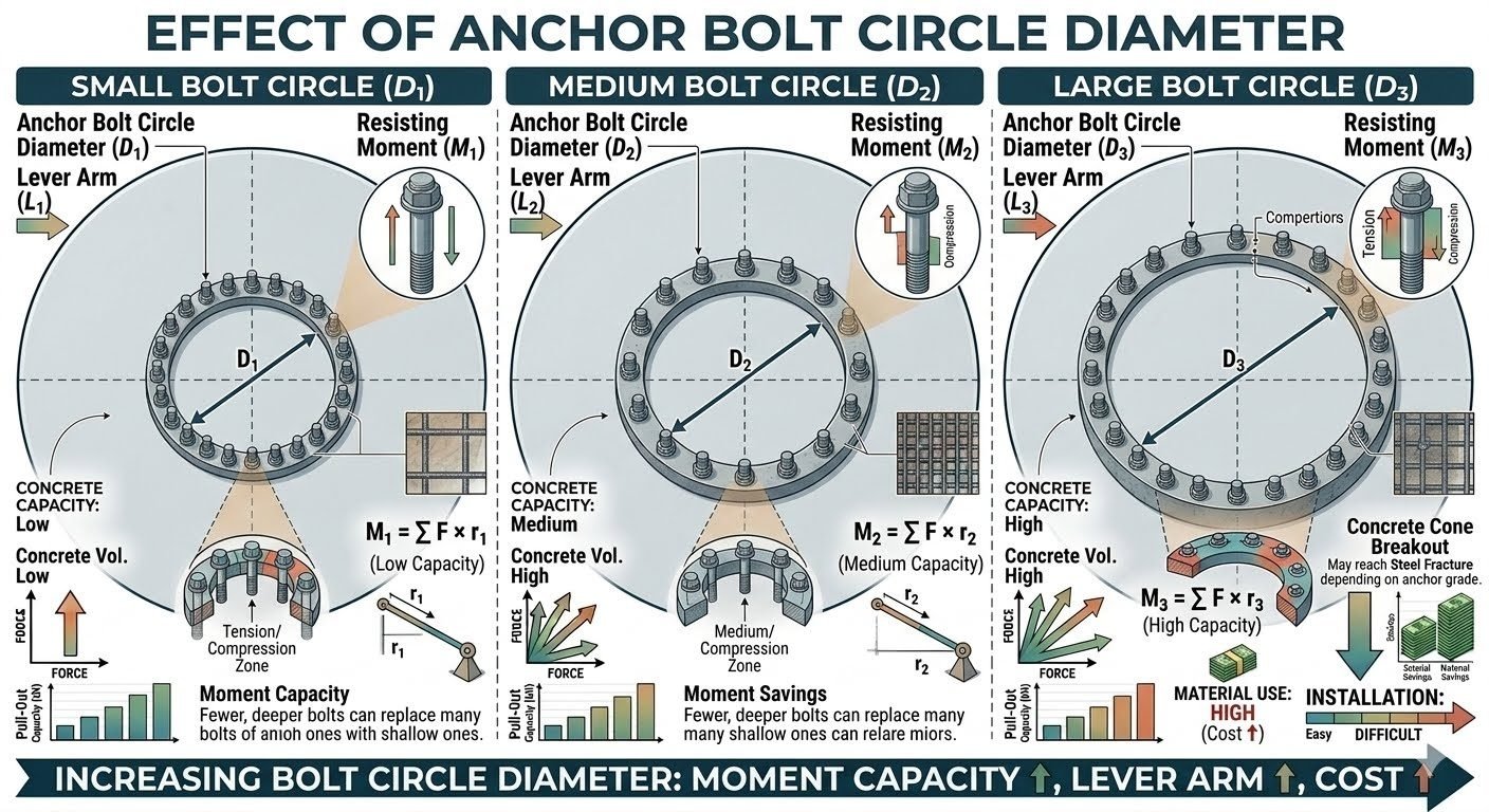
The primary mechanical driver in any base plate connection is the moment arm established by the anchor bolt circle diameter. When an overturning moment M is applied to a vertical vessel or structural column, the base plate rotates about its neutral axis. The resisting moment M_R provided by the anchor bolts is calculated by summing the products of individual bolt tensile forces and their respective radial distances from the neutral axis.

For a small bolt circle configuration denoted as D_1, the resulting lever arm r_1 is inherently tight. Consequently, the low capacity assembly requires high bolt tension forces F to resist overturning moments, expressed mathematically as M_1 = sum (F · r_1). This configuration concentrates stresses into a narrow zone, demanding closely spaced fasteners that frequently complicate field installation and concrete reinforcement placement.

Expanding the layout to a medium bolt circle configuration D_2 increases the lever arm to r_2, resulting in a medium capacity rating where M_2 = sum (F · r_2). The mechanical advantage gained here reduces the peak tensile load required in each individual anchor rod for the same applied overturning moment. Piping engineers often select this median configuration for standard pumps and mid-sized heat exchangers.

Transitioning to a large bolt circle configuration D_3 maximizes the lever arm to r_3, yielding high capacity where M_3 = sum (F · r_3). While this setup provides exceptional overturning resistance and allows structural designers to utilize fewer overall bolts, it introduces severe mechanical penalties. The extended base plate overhang creates massive bending moments within the steel plate itself, requiring thick gussets or heavy plate sections to prevent prying action and excessive deflection.

Design Warning: Base Plate Pry-Out and Flexure

As anchor bolt circle diameter increases, the unsupported span of the base plate between the vessel wall and the bolt circle grows. Without adequate stiffener ribs or increased plate thickness, plate bending will invalidate standard anchor tension assumptions, leading to premature base plate yielding under cyclic wind or seismic loads.

Evaluating these configurations requires strict adherence to AISC Steel Construction Manual provisions and ASME Boiler and Pressure Vessel Code Section VIII requirements. The interaction between concrete breakout strength, anchor embedment depth, and edge distance must be verified using ACI 318 appendix D building code requirements for structural concrete fastenings.

In my professional practice, I always perform comparative finite element checks when scaling up a bolt circle. While the analytical sum of forces suggests linear improvements in moment resistance, local concrete bearing stresses beneath the compression zone of the base plate often reach critical thresholds long before the steel anchor bolts reach their ultimate tensile strength.

Advantages & Disadvantages
Comparative evaluation: A systematic balancing of mechanical benefits and financial drawbacks associated with scaling anchor bolt circle diameters in structural foundations.

Advantages of Large Bolt Circles

  • Substantially increases the internal lever arm, amplifying resisting moment without upgrading bolt material strength.
  • Reduces the total number of anchor bolts required by utilizing higher individual fastener loads at a wider radius.
  • Improves dynamic stability against seismic and wind overturning forces by widening the structural footprint.
  • Alleviates severe congestion of embedded rebar cages in concrete pedestals by spacing anchor rods further apart.
  • Provides better clearance for heavy machinery grouting placement beneath large equipment base plates.

Disadvantages & Cost Impacts

  • Demands significantly thicker base plates and extensive stiffener gussets to resist plate bending over the extended span.
  • Increases total material weight and procurement costs for structural steel and foundation concrete blocks.
  • Complicates field installation accuracy, as larger diameters magnify minor template layout tolerances.
  • Increases thermal expansion mismatch stresses between hot equipment nozzles and wide anchor arrays.
  • Requires heavier rigging equipment to handle oversized prefabricated base assemblies on site.
Real-World Applications
Industrial deployments: Proven engineering implementations of varying anchor bolt circle diameters across heavy process plant infrastructure.

Tall Fractionation Columns in Refineries

Petroleum fractionators and distillation towers experience massive wind-induced overturning moments. Engineers deploy large diameter bolt circle configurations (D_3) to maximize the moment arm, allowing the foundation to withstand extreme hurricane wind loads without requiring unmanageable quantities of clustered anchor bolts.

Centrifugal Compressor Skid Packages

High-speed rotating compressors generate dynamic cyclic forces that require rigid foundation restraint. Medium bolt circle configurations (D_2) are routinely specified on packaged skids to balance vibrational dampening with practical structural steel framing limits under equipment skids.

Vertical Chemical Storage Tanks

Atmospheric storage tanks storing hazardous liquids utilize smaller bolt circle diameters (D_1) combined with numerous perimeter chairs. Because liquid head pressures create uniform radial outward loads rather than overturning moments, tight bolt circles provide optimal sealing and shell anchorage efficiency.

Offshore Topside Flare Booms

Offshore platforms demand extreme structural optimization due to weight constraints. Structural designers utilize optimized large bolt circles on cantilevered flare structures to achieve high moment resistance with minimized structural steel dead weight, complying with strict marine platform safety codes.

Anchor Bolt Circle Diameter Performance Comparison

Anchor bolt circle performance comparison requires rigorous examination of geometric variables, moment resistance, and material expenditure across varying structural scales. In my engineering practice, evaluating structural support configurations for large vertical process vessels governed by ASME Boiler and Pressure Vessel Code and AISC Steel Construction Manual standards reveals clear trade-offs between mechanical advantage and economic viability. The structural database below outlines how small, medium, and large bolt circle diameters dictate foundational design outcomes.

As you review the parameters in the data table, notice how incremental expansions in the bolt circle radius amplify the resisting moment without requiring a proportional increase in individual bolt tensile forces. However, this mechanical efficiency must be balanced against the escalating costs of larger base plates and complex concrete foundation geometry.

Configuration Tier Bolt Circle Diameter (D) Nominal Lever Arm (r) Resisting Moment Capacity Material Cost Index
Small Bolt Circle (D1) 600 mm to 900 mm 300 mm to 450 mm Low (Baseline Capacity) Low (Standard Base Plate)
Medium Bolt Circle (D2) 1200 mm to 1800 mm 600 mm to 900 mm Moderate to High Moderate (Enlarged Gussets)
Large Bolt Circle (D3) 2200 mm to 3500 mm+ 1100 mm to 1750 mm+ Maximum (High Capacity) High (Thick Ring Plates)

Utilizing these metrics ensures that your structural framework avoids both under-designed anchor arrangements prone to fatigue failure and over-engineered assemblies that inflate project budgets unnecessarily.

Technical Mapping & Specifications Matrix

Technical mapping of structural entities provides a standardized vocabulary for piping and foundation engineering teams working across multidisciplinary projects. The specification matrix below correlates structural acronyms, governing calculation variables, and applicable code standards referenced throughout base plate design protocols. In my professional design reviews, cross-referencing these entities guarantees compliance with ASME Section VIII and AISC Design Guide 1 requirements.

Each entry in this matrix highlights a specific physical parameter or mathematical entity that directly influences the calculation of anchor bolt circle diameter and structural moment resistance.

Structural Entity Symbol / Acronym Primary Function Governing Standard
Bolt Circle Diameter BCD (D) Establishes anchor radius and baseline lever arm length AISC Steel Construction
Resisting Moment M Calculates total overturning resistance from bolt tension forces ASME BPVC Section VIII
Lever Arm Radius r Defines perpendicular distance from neutral axis to bolt axis AISC Design Guide 1
Base Plate Thickness tp Resists bending stresses induced by anchor bolt tension ASME STS-1

Reviewing this matrix during the preliminary engineering phase ensures that structural calculations align perfectly with internationally recognized design codes and standard industry nomenclature.

Anchor Bolt Circle Site Verification Checklist

Site verification of anchor bolt circle diameter and base plate assemblies is a critical quality control gate prior to equipment setting and grout placement. In my field engineering experience, overlooking dimensional tolerances or bolt alignment issues during civil handover invariably leads to costly field modifications and project delays. To ensure flawless execution, you must verify every parameter against engineering drawings and applicable standards such as ASME PCC-1 and AISC Manual guidelines.

The comprehensive verification checklist below outlines the exact inspection steps required to validate bolt circle geometry, tension uniformity, and material soundness before final equipment commissioning.

Pre-Installation & Verification Protocol

  • Bolt Circle Diameter Measurement: Verify that the actual installed bolt circle diameter matches the engineering design drawing within permitted tolerances (plus or minus 1.5 mm).
  • Radial Symmetry Check: Confirm angular spacing between adjacent anchor bolts is uniform across the entire circle perimeter to prevent uneven load distribution.
  • Thread Protrusion Inspection: Ensure sufficient thread stick-up above the top nut (minimum two to three threads exposed) in accordance with ASME PCC-1 standards.
  • Base Plate Leveling Validation: Check base plate elevation and leveling shims using a calibrated precision instrument to guarantee even contact across the grout bed.
  • Bolt Tension Verification: Confirm that anchor bolt pre-load torque values match engineering specifications using calibrated torque wrenches or hydraulic tensioning equipment.
  • Non-Destructive Examination (NDE): Verify that all welded anchor chairs and gusset plates have undergone required visual and NDE inspections per ASME Section VIII requirements.

Completing each item on this verification checklist protects structural integrity, prevents fatigue failure under dynamic wind and seismic loads, and ensures long-term operational reliability for critical industrial assets.

Field Case Study: Real-World Application

Real-world engineering challenges often test theoretical design assumptions when unexpected seismic or wind loading conditions occur on operational sites. During the expansion of a major petrochemical facility in the US Gulf Coast region, our engineering team evaluated a severe structural vibration issue on a 45-meter tall fractionator column. The original installation utilized a medium bolt circle diameter (D2) configuration that exhibited excessive deflection and anchor bolt fatigue under high wind-shear moments.

Engineering Problem Encountered

Severe overturning moments caused cyclic tensile stress exceeding allowable fatigue limits in the existing anchor bolt array.

  • Inadequate moment capacity resulting from a constrained lever arm (r2) under extreme hurricane wind loads.
  • Excessive bolt elongation and base plate uplift leading to grout fracturing and water ingress.
  • High localized bending stresses in the base plate due to insufficient gusset stiffness between bolt locations.
  • Failure to meet stringent ASME STS-1 deflection criteria for tall vertical vessels.

Successful Resolution & Outcome

Transitioning to an optimized large bolt circle (D3) configuration combined with deeper, high-strength anchor bolts resolved the structural deficiency entirely.

  • Increased the structural lever arm by 40 percent, directly boosting the resisting moment capacity (M3) without increasing bolt count.
  • Eliminated cyclic bolt fatigue by distributing tensile loads across a wider, more rigid foundation footprint.
  • Enhanced base plate stiffness in compliance with AISC Design Guide 1 recommendations.
  • Passed all post-modification deflection tests and meteorological audits with zero structural anomalies.

My primary recommendation from this project is to always evaluate larger bolt circle configurations early in the FEED phase for tall vertical equipment, ensuring that moment capacity scales appropriately with environmental overturning forces.

Frequently Asked Engineering Questions

How does anchor bolt circle diameter directly impact structural moment capacity?

Increasing the anchor bolt circle diameter extends the mechanical lever arm from the neutral axis, which multiplies the resisting moment capacity for any given bolt tension force following standard structural mechanics principles outlined in ASME PCC-1 guidelines.

  • Larger radii create greater resisting moment arms (M = F multiplied by r).
  • Tensile demands on individual anchor bolts decrease proportionally.
  • Base plate bending moments shift in response to wider fastener spacing.
When should an engineer select a small bolt circle configuration?

A small bolt circle diameter suits compact equipment footprints with lower overturning moments where material cost savings and simplified installation effort take priority over maximum moment resistance.

  • Ideal for vertical vessels under moderate wind or seismic loads.
  • Reduces base plate thickness requirements by minimizing cantilever spans.
  • Simplifies formwork and embedded template alignment during concrete pours.
What are the primary cost implications of upgrading to a large bolt circle?

Expanding the bolt circle diameter significantly increases structural steel mass, fabrication labor, and concrete pedestal dimensions, driving up total project capital expenditure as specified by AISC Steel Construction Manual standards.

  • Larger base plates require thicker cross-sections to prevent prying action.
  • Increased concrete pedestal footprint escalates civil construction expenses.
  • Handling heavier components demands specialized heavy lifting equipment on-site.
How does bolt circle sizing affect base plate thickness design?

Wider bolt circles extend the distance between the anchor bolts and the column or vessel wall, creating longer cantilever spans that increase bending moments within the base plate itself.

  • Bigger cantilever distances demand thicker plates or added stiffener ribs.
  • Stiffeners help distribute loads evenly without excessive plate deflection.
  • Engineers must balance bolt circle radius against plate weight penalties.
Can fewer deep-set bolts at a larger radius replace many small bolts?

Deploying a smaller number of high-capacity bolts positioned on a larger circle diameter can successfully match or exceed the moment resistance of dense, small-circle fastener arrays while reducing overall hardware count.

  • Lever arm gains compensate for reduced fastener quantity.
  • Fewer holes to drill and align speed up shop fabrication times.
  • Requires rigorous verification of concrete breakout strength per code rules.

Field Recommendation

Based on my two decades of piping and structural design experience, optimizing anchor bolt circle geometry requires balancing mechanical demands with practical site constraints. Here is my professional guidance for upcoming installations:

  • If designing tall columns subject to severe wind loads, choose a large bolt circle (D3) configuration to maximize the resisting lever arm, keeping individual bolt tension within allowable ASME limits despite higher steel costs.
  • If working on skid packages with strict spatial limits, select a medium bolt circle (D2) configuration to achieve a reliable compromise between moment capacity and base plate footprint without overcrowding the structural frame.
  • When heavy material expenditure is flagged during early estimating, replace a high-density small-circle bolt array with fewer, larger-diameter fasteners placed at an expanded radius to capture material savings while maintaining structural integrity.
  • Always verify concrete pedestal edge distances when expanding bolt circle diameters on site, ensuring that the wider anchor placement does not violate minimum breakout requirements under ACI 318 provisions.

Complete Course on
Piping Engineering

Check Now

Key Features

  • 125+ Hours Content
  • 500+ Recorded Lectures
  • 20+ Years Exp.
  • Lifetime Access

Coverage

  • Codes & Standards
  • Layouts & Design
  • Material Eng.
  • Stress Analysis
Atul Singla - Piping EXpert

Atul Singla

Senior Piping Engineering Consultant

Bridging the gap between university theory and EPC reality. With 20+ years of experience in Oil & Gas design, I help engineers master ASME codes, Stress Analysis, and complex piping systems.