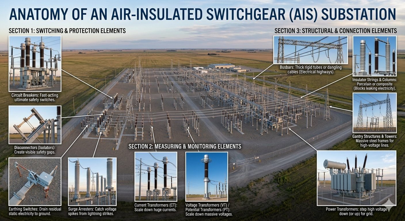
Mastering AIS Substation Components for Grid Reliability
In my two decades of experience navigating high-voltage infrastructure, I have found that the Air Insulated Substation (AIS) remains the backbone of global power distribution. Unlike Gas Insulated Substations (GIS), AIS relies on atmospheric air as the primary dielectric medium, which demands a rigorous understanding of clearances, creepage distances, and structural integrity.
Designing an AIS requires balancing the physical footprint with the electrical performance of critical assets like circuit breakers and busbar systems. Whether you are managing a greenfield project or retrofitting an aging facility, the interaction between these components dictates the overall reliability of the grid.
Key Takeaways for Substation Design:
- Understand the functional hierarchy: Switching, Protection, and Structural elements.
- Ensure strict adherence to IEC 61936-1 for safety clearances.
- Prioritize maintenance access for disconnectors and earthing switches.
- Optimize busbar configurations to minimize electromagnetic stress during fault conditions.
Technical Analysis of AIS Substation Components
AIS Substation Components: These elements are engineered to manage high-voltage energy through precise mechanical switching and electromagnetic transformation, governed by strict international safety protocols.
Switching and Protection Dynamics
The switching section is the heart of the substation. Circuit breakers are designed to interrupt fault currents, often exceeding 40kA, within milliseconds. In my experience, the selection of the quenching medium—typically SF6 gas or vacuum—is critical for arc extinction. The IEC 62271 series provides the testing parameters for these devices, ensuring they can withstand the transient recovery voltage (TRV) that occurs immediately after current interruption.
Disconnectors, or isolators, provide the visible break required for maintenance. Unlike breakers, they are not designed to interrupt load current. I always emphasize that the interlocking mechanism between the breaker and the disconnector is the most vital safety feature in the bay. If an operator attempts to open a disconnector under load, the resulting arc can be catastrophic.
Measuring and Monitoring Infrastructure
Current Transformers (CTs) and Voltage Transformers (VTs) serve as the eyes of the substation. They scale primary high-voltage signals down to manageable levels (typically 1A/5A for CTs and 110V/root 3 for VTs) for protective relays and metering equipment. The accuracy class of these transformers is paramount; a deviation in the secondary signal can lead to nuisance tripping or inaccurate billing.
Engineering Warning: Insulation Coordination
Failure to maintain proper phase-to-phase and phase-to-ground clearances as defined in IEC 61936-1 will lead to flashovers. Always account for altitude correction factors and pollution levels when calculating the required creepage distance for insulator strings.
Structural Integrity and Busbar Design
Busbars act as the electrical highway. Whether using rigid aluminum tubes or flexible stranded conductors, the design must account for thermal expansion and short-circuit electromagnetic forces. When calculating the mechanical stress on busbar supports, I use the formula for force per unit length: F = (mu_0 * I^2) / (2 * pi * d), where I is the fault current and d is the distance between phases.
Gantry structures must be designed to support the static weight of the conductors and the dynamic loads imposed by wind and ice. In seismic zones, the structural steel must be reinforced to prevent resonance during an earthquake, which could otherwise lead to the failure of brittle porcelain insulators.
AIS Substation Performance: These systems offer a balance of cost-effectiveness and operational visibility, though they require significant physical space and environmental protection.
Advantages
- Lower initial capital expenditure compared to GIS.
- Visible isolation points enhance operator safety during maintenance.
- Easier to expand or modify existing bay configurations.
- No risk of SF6 gas leakage into the atmosphere.
- Simplified maintenance procedures for structural components.
Disadvantages
- Requires a significantly larger land footprint.
- High susceptibility to environmental factors like salt, dust, and humidity.
- Insulators require frequent cleaning in polluted areas.
- Increased risk of wildlife-induced short circuits.
- Higher susceptibility to lightning-related transient surges.
AIS Substation Deployment: These configurations are utilized across diverse industrial and utility sectors where space is available and reliability is non-negotiable.
Utility Transmission Substations
Large-scale transmission substations utilize AIS to step down voltages from 400kV to 132kV. These sites rely on massive gantry structures and robust circuit breakers to maintain grid stability across regional networks.
Renewable Energy Integration
Wind and solar farms often employ AIS for their collector substations. Because these projects are typically located in rural areas with ample land, the footprint of an AIS is not a constraint, making it the most economical choice.
Heavy Industrial Facilities
Steel mills and mining operations require dedicated substations to handle high-load demands. AIS provides the necessary flexibility to integrate complex protection schemes and monitoring equipment directly into the plant’s power distribution loop.
In my two decades of field experience, selecting the correct AIS substation components requires a rigorous evaluation of electrical and mechanical stress parameters. The following table outlines the critical design ratings that engineers must reconcile against IEC 62271 standards to ensure long-term grid stability and safety.
These parameters dictate the physical footprint and insulation coordination requirements for the entire switchyard. Failure to align these ratings with site-specific short-circuit levels often leads to premature equipment degradation or catastrophic failure during transient events.
| Component Type | Primary Rating Metric | Standard Reference |
|---|---|---|
| Circuit Breakers | Short-Circuit Breaking Current (kA) | IEC 62271-100 |
| Disconnectors | Rated Short-Time Withstand Current | IEC 62271-102 |
| Surge Arresters | Nominal Discharge Current (kA) | IEC 60099-4 |
| Current Transformers | Accuracy Class & Burden (VA) | IEC 61869-2 |
Engineers should note that the “Rated Short-Time Withstand Current” is the most critical value for busbars and disconnectors. This value represents the thermal and mechanical stress the component must endure during a fault before the protection system clears the circuit.
The integration of AIS substation components relies on a complex matrix of electrical, mechanical, and environmental variables. This mapping ensures that every piece of equipment, from the smallest insulator to the largest power transformer, functions as a cohesive unit within the IEC 61936-1 framework.
By categorizing these entities, we can better visualize the dependencies between primary power flow and secondary monitoring systems. This matrix serves as a foundational reference for procurement and site installation planning.
| Entity Category | Key Acronym | Standard Compliance |
|---|---|---|
| Switching Elements | CB / DS / ES | IEC 62271 |
| Measurement Units | CT / VT / PT | IEC 61869 |
| Structural Steel | Gantry / Tower | ISO 1461 |
| Insulation Systems | BIL / SIL | IEC 60071 |
The Basic Insulation Level (BIL) is the primary metric for determining the clearance distances between live parts and grounded structures. Maintaining these distances is non-negotiable for preventing flashovers in high-altitude or high-pollution environments.
Verification of AIS substation components requires a systematic approach to ensure that every installation meets the design specifications and safety requirements defined by IEC 61936-1. In my experience, the most common failures occur during the commissioning phase due to overlooked mechanical alignments or improper grounding connections.
This checklist is designed to guide site engineers through the final verification of primary equipment before energization. It covers the mechanical integrity of support structures, the electrical continuity of busbar systems, and the calibration of protection monitoring devices.
- 1. Verify that all circuit breaker operating mechanisms are lubricated and tested for rated opening/closing times per IEC 62271-100.
- 2. Confirm that all disconnector blades achieve full contact engagement and that the visible gap meets safety clearance requirements.
- 3. Inspect surge arrester ground leads for low-impedance paths and ensure the discharge counters are functional.
- 4. Validate that current transformer secondary circuits are properly shorted if not connected to a load to prevent high-voltage buildup.
- 5. Check all gantry structure bolts for proper torque and ensure that the galvanization layer is free from site-induced damage.
- 6. Confirm that all insulator strings are cleaned of construction dust and debris to prevent tracking during initial energization.
Following these steps ensures that the substation is not only compliant with international standards but also resilient against the harsh environmental conditions typical of outdoor switchyards. Always document every test result in the site logbook for future maintenance reference.
Problem: Premature Insulator Flashover in Coastal AIS Substation
A 220kV AIS substation experienced repeated flashovers on porcelain insulator strings during high-humidity conditions, leading to unplanned outages.
- Accumulation of salt spray on insulator surfaces due to proximity to the coastline.
- Inadequate creepage distance for the specific pollution level (Class IV) of the site.
- Lack of regular cleaning schedules for the insulator strings.
- Corrosion of the metal caps on the insulator columns, reducing structural integrity.
Outcome: Successful Mitigation and Reliability Restoration
The engineering team implemented a comprehensive remediation strategy that restored grid reliability and eliminated flashover events.
- Replacement of standard porcelain insulators with high-creepage silicone rubber composite insulators.
- Application of RTV (Room Temperature Vulcanizing) silicone coating to existing structures.
- Installation of a dedicated washing system for periodic maintenance.
- Revision of the maintenance manual to include quarterly inspections of insulator surface conditions.
My recommendation for similar environments is to prioritize the selection of composite insulators during the design phase. While the initial capital expenditure is higher, the reduction in maintenance costs and the prevention of costly downtime provide a superior return on investment over the substation lifecycle.
Frequently Asked Engineering Questions
What are the primary switching and protection elements in an AIS substation?
- Circuit Breakers: Interrupt high-fault currents rapidly to protect downstream assets.
- Disconnectors/Isolators: Provide a visible physical air gap for maintenance safety.
- Surge Arresters: Divert high-voltage lightning and switching surges directly to the ground grid.
How do measuring and monitoring elements comply with IEC 61936-1 standards?
- Current Transformers (CTs): Step down primary currents to 1A or 5A secondary outputs.
- Voltage Transformers (VTs): Reduce primary kilovolts to 110V secondary levels for metering.
- Compliance: Must meet clearance and accuracy class requirements specified in IEC 61936-1.
What role do structural and connection elements play in substation design?
- Busbars: Act as high-current electrical highways connecting different bays.
- Gantry Structures: Support incoming overhead transmission lines and withstand heavy wind loads.
- Insulator Strings: Prevent leakage currents from traveling down steel support towers to the ground.
Why are earthing switches critical for maintenance safety in AIS layouts?
- Static Discharge: Safely evacuates capacitive charges remaining on long bus sections.
- Accidental Re-energization: Creates a solid ground path to trigger upstream breakers if the line is energized.
- Interlocking: Mechanically interlocked with disconnectors to prevent closing on live lines.
How do environmental clearances affect the spacing of AIS substation components?
- Phase Clearances: Determined by the system’s rated lightning impulse withstand voltage (BIL).
- Ground Clearances: Prevent accidental contact with vehicles, personnel, or maintenance equipment.
- Environmental Factors: Spacing must increase in high-pollution or high-altitude zones per IEC 61936-1.
Complete Course on
Piping Engineering
Check Now
Key Features
- 125+ Hours Content
- 500+ Recorded Lectures
- 20+ Years Exp.
- Lifetime Access
Coverage
- Codes & Standards
- Layouts & Design
- Material Eng.
- Stress Analysis
