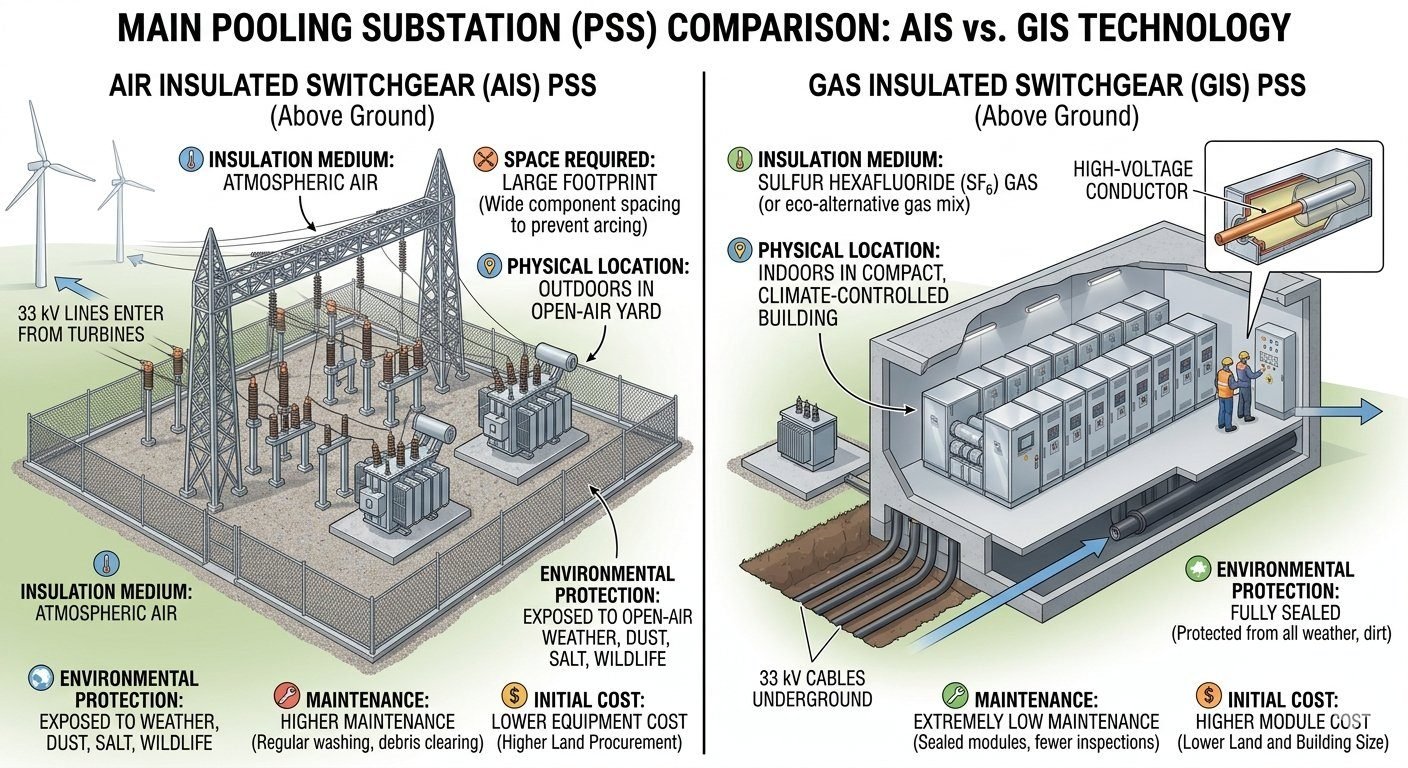
AIS vs GIS Substation: Choosing the Best Technology
In my 20+ years of executing high-voltage substation projects, I have watched many developers make the mistake of looking only at the initial purchase price of switchgear. When you are designing a Main Pooling Substation (PSS) for a wind or solar farm, the choice between Air-Insulated Switchgear (AIS) and Gas-Insulated Switchgear (GIS) dictates your entire civil engineering budget, land acquisition strategy, and maintenance schedule for the next thirty years.
I always tell my teams that a cheap AIS system can quickly become an operational nightmare in coastal or high-dust environments, while an over-engineered GIS system can kill a project’s financial viability before ground is even broken. We must look at the physical physics of insulation, environmental degradation, and real-world lifecycle costs to make an informed decision.
- GIS reduces the physical footprint by up to 80% compared to AIS.
- AIS offers lower initial capital expenditure but requires frequent maintenance.
- Environmental factors like salinity and dust dictate the optimal technology choice.
How to Evaluate an AIS vs GIS Substation
The fundamental difference between these two systems lies in the dielectric strength of the insulating medium. Air-Insulated Switchgear relies on atmospheric air, which has a breakdown strength of approximately 30 kV per centimeter under standard conditions. This low dielectric strength forces us to design massive clearance distances between phase conductors and grounded structures.
In contrast, Gas-Insulated Switchgear utilizes sulfur hexafluoride (SF6) gas, which possesses a dielectric strength roughly three times higher than air at atmospheric pressure. When pressurized to 0.4 to 0.6 MPa (4 to 6 bar) inside the switchgear enclosure, the dielectric strength of SF6 increases to nearly ten times that of air. This physical property allows us to bring high-voltage conductors incredibly close together without the risk of flashovers.
Key Parameters of an AIS vs GIS Substation
Let us look at the mathematical reality of these clearance requirements. For a standard 220 kV system, the Basic Insulation Level (BIL) is typically rated at 1050 kV. In an AIS installation, the minimum phase-to-earth clearance required by code is 2100 millimeters. This physical separation, combined with the space needed for maintenance access and safety barriers, results in a typical bay width of 15 meters.
When we design the same 220 kV system using GIS, the pressurized SF6 gas allows us to reduce the phase-to-earth clearance inside the metal enclosure to less than 200 millimeters. The entire three-phase switchgear bay can be packaged into a modular assembly that is only 2.4 meters wide. This represents a massive reduction in physical volume and land requirements.
Environmental exposure is another critical factor that I always analyze during the front-end engineering design (FEED) phase. Because AIS equipment is completely exposed to the elements, it suffers from continuous environmental degradation. In coastal areas, salt spray deposits a conductive layer on porcelain and composite insulators, which drastically reduces their creepage resistance.
To prevent tracking and flashovers in polluted environments, we must calculate the required specific creepage distance. For a heavy pollution zone (Class IV per IEC 60815), the required creepage distance is 31 millimeters per kilovolt of highest system voltage. For a 220 kV system (maximum voltage 245 kV), this requires a total creepage distance of:
Creepage Distance = 245 kV x 31 mm/kV = 7595 mm
Achieving this creepage distance requires extremely long, heavy insulator strings, which in turn increases the structural load on the steel gantry structures. With GIS, the active contacts are sealed inside a dry, pressurized aluminum or steel enclosure. The external environment has zero impact on the internal dielectric performance, eliminating the need for regular insulator washing and contact maintenance.
From a structural perspective, AIS installations require extensive civil works. The tall steel gantries and dead-end towers must withstand high wind loads and seismic forces. The wind force on the conductors and structures is calculated using the standard formula:
F = q_z x G x C_f x A_f
Where q_z is the velocity pressure, G is the gust effect factor, C_f is the force coefficient, and A_f is the projected area. Because of the large physical profile of AIS equipment, these wind forces generate massive overturning moments at the foundation level, requiring deep concrete piles or heavy spread footings. GIS equipment is housed indoors, shielding it entirely from wind loads and allowing for much simpler, flat-slab foundation designs.
- Footprint Reduction: Saves up to 80% of land area, lowering civil preparation and land acquisition costs.
- Environmental Immunity: Sealed SF6 chambers protect contacts from salt, dust, and moisture.
- Enhanced Safety: Metal-enclosed design prevents accidental contact with live parts during operation.
- Low Maintenance: Requires major maintenance only after 20+ years, compared to annual AIS checks.
- Seismic Resilience: Low center of gravity makes GIS highly resistant to earthquake damage.
- High Initial CapEx: Equipment costs are significantly higher than open-air AIS.
- SF6 Environmental Risk: Potential gas leaks require continuous monitoring and reporting.
- Longer Repair Times: Internal faults require specialized gas handling and cleanroom conditions.
- Building Requirement: Must be housed in a climate-controlled indoor building.
- Extension Difficulty: Adding new bays requires matching the original manufacturer’s design.
Selecting between Air-Insulated Switchgear (AIS) and Gas-Insulated Switchgear (GIS) requires a rigorous evaluation of site-specific constraints. In my experience, the primary driver for choosing GIS is the drastic reduction in physical footprint, often achieving a 70% to 90% space saving compared to traditional AIS layouts. This is achieved because sulfur hexafluoride (SF6) gas possesses a dielectric strength significantly higher than atmospheric air, allowing for much smaller phase-to-phase and phase-to-ground clearances as defined by IEC 62271 standards.
Conversely, AIS remains the industry standard for projects where land availability is abundant and capital expenditure (CapEx) must be strictly minimized. While AIS requires larger clearances to prevent flashovers, the simplicity of the design allows for easier visual inspection and modular expansion. The following table outlines the critical technical parameters that dictate the selection process for a Main Pooling Substation.
| Parameter | AIS (Air-Insulated) | GIS (Gas-Insulated) |
|---|---|---|
| Insulation Medium | Atmospheric Air | SF6 Gas |
| Footprint Requirement | High (100%) | Low (10-30%) |
| Environmental Sensitivity | High (Pollution/Humidity) | Negligible (Sealed) |
| Initial CapEx | Lower | Higher |
| Maintenance Frequency | Frequent/Periodic | Low/Condition-Based |
Engineers must also consider the lifecycle cost, as the lower maintenance requirements of GIS often offset the higher initial investment over a 25-year operational horizon. When evaluating these systems, always reference the IEEE C37 series for specific testing protocols and safety requirements.
The integration of high-voltage switchgear into a Main Pooling Substation involves complex interactions between electrical, mechanical, and environmental variables. To ensure system reliability, engineers must map these variables against established international standards. This matrix provides a structural overview of the key entities involved in the design and procurement phase of substation development.
By categorizing these entities, we can better understand the trade-offs between AIS and GIS technologies. For instance, the dielectric integrity of GIS is governed by strict pressure monitoring, whereas AIS relies on creepage distance and insulator cleaning cycles to maintain performance in coastal or industrial environments.
| Entity | Standard Reference | Primary Function |
|---|---|---|
| SF6 Gas | IEC 62271-203 | Dielectric insulation and arc quenching |
| Bushings | IEEE C57.19 | High-voltage terminal insulation |
| Circuit Breakers | IEC 62271-100 | Fault current interruption |
| Disconnectors | IEC 62271-102 | Isolation for maintenance safety |
This matrix serves as a foundational guide for procurement teams and design engineers. By aligning project requirements with these specific standards, you ensure that the chosen switchgear technology meets the necessary safety and performance benchmarks for long-term grid stability.
Before finalizing the selection of AIS or GIS for a Main Pooling Substation, I conduct a comprehensive site verification process. This ensures that the chosen technology aligns with the physical, environmental, and economic realities of the project site. Failure to account for these factors during the FEED (Front-End Engineering Design) stage often leads to costly change orders or operational bottlenecks.
Substation Technology Selection Checklist
- ✓ Evaluate total available land area against the required AIS clearance distances.
- ✓ Assess local environmental conditions, specifically salt spray, industrial pollution, or high humidity.
- ✓ Calculate the 25-year Total Cost of Ownership (TCO) including maintenance and potential SF6 handling costs.
- ✓ Verify seismic zone requirements and structural support capabilities for the chosen switchgear.
- ✓ Confirm availability of skilled personnel for specialized GIS maintenance and gas handling.
- ✓ Review local regulatory compliance regarding SF6 gas reporting and environmental impact.
Each item on this checklist must be documented in the project design basis. For instance, if the site is located in a high-pollution area, the cost of frequent insulator washing for AIS may quickly exceed the initial capital premium of a GIS installation. Always prioritize safety and reliability, ensuring that the design complies with IEC 62271 standards for high-voltage switchgear and controlgear.
Problem: Coastal Substation Reliability Issues
A major utility faced recurring flashovers at a coastal AIS pooling station due to severe salt-laden fog and high humidity levels.
- Frequent insulator tracking leading to phase-to-ground faults.
- High operational costs associated with manual insulator cleaning cycles.
- Increased risk of unplanned outages during peak load periods.
- Corrosion of exposed metallic structures due to the saline environment.
Outcome: GIS Retrofit Success
The decision to replace the AIS with a compact GIS module resolved the environmental exposure issues and improved grid reliability.
- Eliminated flashovers by enclosing all live parts in a sealed, SF6-insulated environment.
- Reduced maintenance requirements by 85% compared to the previous AIS setup.
- Minimized the physical footprint, allowing for future expansion within the existing site boundary.
- Improved safety for personnel by eliminating exposure to high-voltage components.
My recommendation for similar projects is to perform a thorough environmental audit early in the design phase. If the site is prone to extreme weather or pollution, the long-term reliability of GIS often justifies the initial investment, providing a more robust solution for critical infrastructure.
Frequently Asked Engineering Questions
How do footprint requirements compare between AIS vs GIS Substation layouts for high-voltage pooling stations?
- Phase-to-phase clearance distances decrease from meters in atmospheric air down to millimeters inside gas enclosures.
- Indoor GIS eliminates wide outdoor safety buffer zones required for high-voltage overhead buses.
- Compact footprint reduces site grading and civil works on sloped or high-cost land parcels under IEC 62271-203 standards.
What are the key CapEx and OpEx trade-offs between Air-Insulated and Gas-Insulated Switchgear?
- CapEx: AIS equipment supply costs 30% to 50% less upfront and avoids constructing a specialized climate-controlled building.
- OpEx: GIS cuts routine insulator washing, contact maintenance, and atmospheric corrosion repairs by nearly 70%.
- Lifecycle Value: GIS limits unscheduled revenue losses from pollution flashovers per IEEE C37.122 design benchmarks.
How does atmospheric environmental exposure impact long-term AIS vs GIS Substation reliability?
- AIS Exposure: Outdoor phase conductors, disconnectors, and bushings suffer from airborne dust, salt spray, ice buildup, and wildlife intrusion.
- GIS Protection: Active high-voltage components remain sealed inside grounded metal housings filled with dry insulating gas.
- Reliability Profile: Sealed GIS maintains stable dielectric clearance regardless of surrounding industrial pollution or ambient humidity.
What environmental compliance and gas-handling protocols are required for SF6 in GIS?
- Leak Monitoring: Automated density switches track pressure changes across independent gas compartments to prevent fugitive emissions.
- Maintenance Protocols: Field technicians must use dedicated gas carts for evacuation and recycling per IEC 62271-303 safety standards.
- Safety Systems: Pressure-relief burst discs direct internal arc gases into safe venting channels inside the switchgear room.
Which switchgear option provides better structural resistance in high-seismic or severe weather regions?
- Seismic Performance: Rigid indoor GIS assemblies lower overturning moments and prevent porcelain bushing stress fractures during earth tremors.
- Weather Immunity: Enclosed switchgear buildings shield primary breakers completely from hurricane winds, extreme icing, and ambient thermal swings.
- Foundation Efficiency: Concentrated equipment layout simplifies localized base-isolation pad design in high-seismic zones.
Complete Course on
Piping Engineering
Check Now
Key Features
- 125+ Hours Content
- 500+ Recorded Lectures
- 20+ Years Exp.
- Lifetime Access
Coverage
- Codes & Standards
- Layouts & Design
- Material Eng.
- Stress Analysis
