What is an Air Relief Valve: Comprehensive Engineering Guide 2026
You are standing next to a 24-inch water transmission main when a sudden, rhythmic thumping starts vibrating through the concrete floor. This isn’t just noise; it is the sound of air binding choking your flow capacity or, worse, a vacuum pocket threatening to implode your pipeline like a soda can.
Properly specifying an Air Relief Valve is the difference between a high-efficiency fluid system and a catastrophic infrastructure failure. This guide breaks down the physics of air management to ensure your assets remain pressurized and protected.
Key Engineering Takeaways
- Triple Functionality: Modern valves manage bulk air intake, large-volume venting, and continuous pressurized release.
- Surge Mitigation: Eliminating trapped air pockets reduces the risk of water hammer and transient pressure spikes.
- Efficiency Gains: Removing air “slugs” can reduce pumping energy costs by up to 15% by restoring the full hydraulic cross-section.
What is an Air Relief Valve?
An Air Relief Valve is a specialized hydromechanical device designed to automatically release entrapped air from a pressurized pipeline and admit air during vacuum conditions. By managing air pockets at high points, these valves prevent air binding, maintain hydraulic efficiency, and protect the system from structural collapse during drainage.
“In my 20 years of pipeline forensics, I have seen more pipe bursts caused by poorly placed air valves than by actual overpressure. Most engineers forget that air is 800 times less dense than water; if you don’t give it a way out, it will find a way to break your system.”
— Atul Singla, Founder of EPCLand
Complete Course on
Piping Engineering
Check Now
Key Features
- 125+ Hours Content
- 500+ Recorded Lectures
- 20+ Years Exp.
- Lifetime Access
Coverage
- Codes & Standards
- Layouts & Design
- Material Eng.
- Stress Analysis
Engineering Knowledge Check: Air Relief Valve Mastery
Test your understanding of AWWA C512 standards and fluid mechanics.
Question 1 of 5
What is the primary function of a “Vacuum Breaker” feature in an Air Relief Valve?
Working Principle of an Air Relief Valve
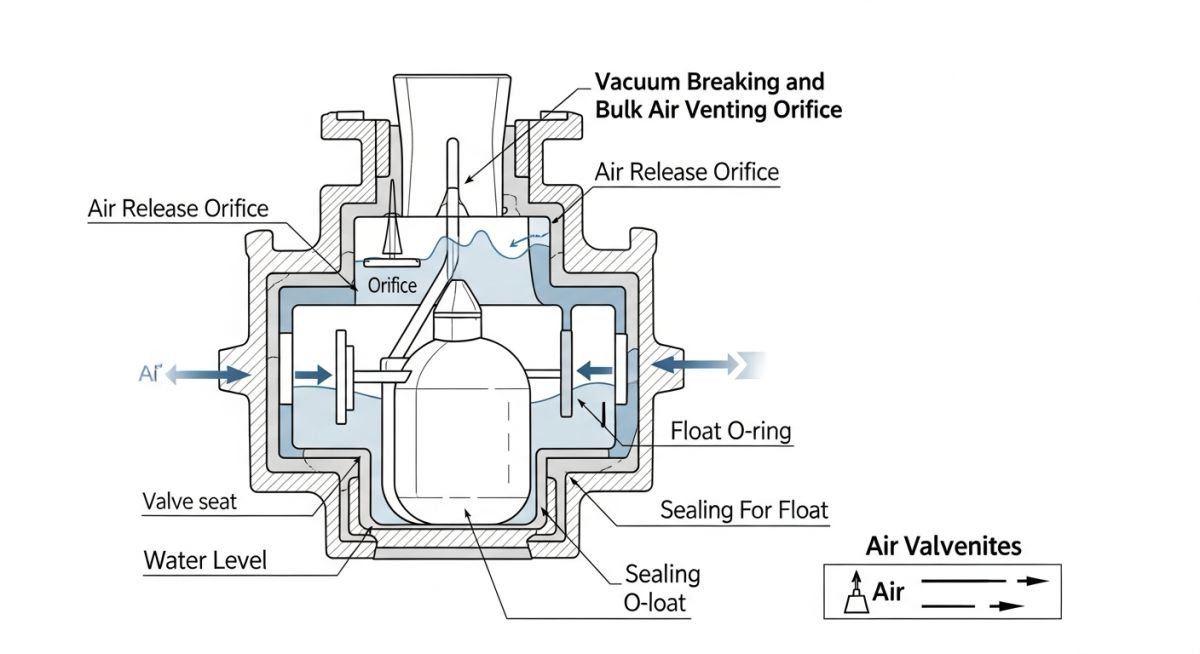
The operational physics of an Air Relief Valve rely on the fundamental principle of buoyancy and the density differential between air and water. In a typical pipeline startup, the line is filled with air. As water enters, it displaces this air, pushing it toward high points. The Air Relief Valve remains open initially, allowing large volumes of air to escape through a large orifice (Kinetic function). Once the water reaches the valve chamber, the internal buoyant float rises, sealing the orifice against a precision-engineered seat to prevent fluid leakage.
However, the process does not end once the line is filled. During standard operation, air dissolved in the water (at roughly 2% by volume) begins to come out of solution due to temperature shifts or pressure drops. these small bubbles migrate to the high points where the Air Relief Valve is installed. As air accumulates in the valve body, the water level drops, causing the float to fall away from the small orifice. This “pressure air release” function ensures that the hydraulic cross-section of the pipe remains 100% liquid, preventing the “air binding” effect that drastically increases friction losses and pumping costs.
Critical Components of an Air Relief Valve
To maintain reliability under harsh industrial conditions, the construction of an Air Relief Valve must adhere to rigorous material standards such as those found in the AWWA C512 Standard. Each component plays a vital role in the valve’s lifecycle:
- Valve Body and Cover: Usually constructed from high-strength Ductile Iron (ASTM A536) to withstand transient pressure surges. The interior is often epoxy-coated to prevent corrosion from stagnant air-water interfaces.
- Buoyant Float: The heart of the valve. Typically made of 316 Stainless Steel or high-density plastic, it must be perfectly spherical and weighted to ensure it drops even when high-velocity air is rushing past it (preventing premature shut-off).
- Orifice and Seat: The sealing interface. For pressurized air release, a Vitron or EPDM resilient seat is used to ensure a bubble-tight seal against the float.
- Cowls and Screens: External components that prevent insects, debris, or birds from nesting in the vent, which could block air intake during a vacuum event.
Advanced Air Relief Valve designs also incorporate a “dual-orifice” or “triple-function” arrangement. This includes a large orifice for bulk air movement and a second, much smaller orifice (often 1/16 to 1/8 inch) specifically for releasing air while the system is under full operating pressure. Without this small orifice, the valve would be unable to open against the high internal pressure of the line once the initial filling is complete.
Standard Engineering Installation for Air Relief Valve Systems
The efficacy of an Air Relief Valve is 90% dependent on its spatial positioning within the hydraulic profile. According to ASME B31.3 Process Piping and AWWA M51 manual, valves must be placed at every significant “high point” where the pipeline slope changes from positive to negative. However, a common engineering oversight is neglecting “long horizontal runs.” In these segments, an Air Relief Valve should be installed every 500 to 1,000 meters to prevent the accumulation of pocketed air that can cause “slug flow” and unpredictable pressure transients.
When installing, the valve must be mounted vertically on a riser at the 12 o’clock position of the pipe. A full-port isolation ball valve or gate valve must be installed between the pipeline and the Air Relief Valve to allow for maintenance without shutting down the entire system. Failure to use a full-port isolation valve can create turbulence that interferes with the float’s buoyancy, leading to premature closure or “shuttering.”
Industrial Applications for Air Relief Valve Technology
While most commonly associated with municipal water works, Air Relief Valve technology is critical across several high-stakes industries. In Wastewater Management, specialized “short-body” valves with conical bottoms are used to prevent solids from clogging the mechanism. In Petrochemical Refineries, these valves are essential for “pigging” operations where air is used to push product through lines, requiring rapid venting at the receiving end.
| Feature | Standard Air Valve | Sewage Air Valve | Vacuum Breaker Only |
|---|---|---|---|
| Primary Medium | Potable / Clean Water | Raw Sewage / Slurry | Industrial Process Fluids |
| Body Geometry | Compact / Cylindrical | Elongated / Conical | Large Orifice / Short |
| Float Material | SS304 / SS316 | Reinforced Polypropylene | Lightweight Composite |
| Key Standard | AWWA C512 | ISO 9001 / Specialized | ASME Section VIII |
Advantages of Air Relief Valve Integration
Implementing a robust Air Relief Valve strategy yields immediate operational dividends:
- Full Hydraulic Flow: Eliminates air pockets that restrict the effective internal diameter of the pipe.
- Surge Suppression: Softens the impact of “water column separation” during pump trips.
- Structural Integrity: The vacuum-breaking function prevents the pipe from collapsing inward during rapid drainage or line breaks.
Potential Disadvantages of Air Relief Valve Misapplication
While essential, a poorly maintained Air Relief Valve can become a liability. If the float seals are compromised, the valve will leak fluid, leading to local flooding or contamination. Furthermore, if a valve is undersized, the air escaping at supersonic speeds can cause the float to “slam” into the seat, generating a secondary surge known as “Air Valve Slam,” which can be just as damaging as the water hammer it was intended to prevent.
EPCLand YouTube Channel
2,500+ Videos • Daily Updates
Air Relief Valve Sizing Calculator (Estimation)
Use this tool to estimate the required Air Relief Valve inlet size based on the AWWA M51 recommendation (2% of pipe diameter rule-of-thumb for standard filling/venting).
Recommended Nominal Size
—
Engineering Case Study: Vacuum Protection in Transmission Mains
Preventing Pipeline Implosion during Rapid Drainage
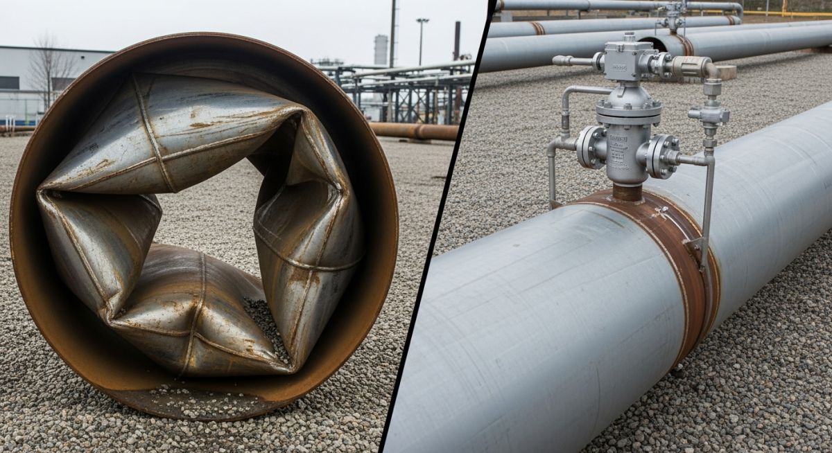
The Scenario (The Failure)
In a 36-inch carbon steel raw water line, a power failure caused a sudden pump trip. As the water column retreated down the hydraulic grade, a massive vacuum formed at the highest elevation point. Because the existing Air Relief Valve had a seized float due to mineral scaling, it failed to open and admit air.
Result: The external atmospheric pressure exceeded the pipe’s buckling strength, causing a 40-foot section to collapse inward, resulting in $450,000 in emergency repair costs.
The Solution (The Engineering Fix)
The damaged section was replaced and retrofitted with a Triple Function Air Relief Valve compliant with AWWA C512. The new design featured a “Non-Slam” kinetic float and a large vacuum-breaker orifice sized to admit 100% of the pipe’s potential drainage flow rate.
Outcome: Subsequent simulated pump trips showed zero vacuum formation, as the valve immediately opened to maintain internal pressure at atmospheric levels.
Lesson Learned
Never treat an Air Relief Valve as a “set and forget” component. Routine cycling of the isolation valve and annual inspections of the float seat are mandatory for critical transmission infrastructure to prevent catastrophic vacuum-induced failures.
Expert Insights: Lessons from 20 years in the field
Beware of “Air Valve Slam”: In high-head systems, if you use a standard Air Relief Valve, the air can exhaust too quickly, causing the water column to accelerate and slam the float shut. Always specify a “Non-Slam” or “Slow Closing” device for lines exceeding 5 meters per second filling velocity.
Placement is everything: Do not just look at high points. Install an Air Relief Valve every 600 meters on flat terrain. Air bubbles tend to merge into large “slugs” that can create significant head loss even in perfectly horizontal pipes.
Material Selection for Longevity: For coastal or corrosive environments, skip the standard ductile iron. Specify 316 Stainless Steel internals and a fusion-bonded epoxy coating to prevent the float from sticking to the seat due to salt-air oxidation.
