Guide to Air Insulated Switchgear Grid Protection
Over my 20 years in industrial plant design, I have integrated countless high-voltage systems. While gas-insulated alternatives have their place, the sheer reliability and straightforward maintenance of air insulated switchgear make it the backbone of heavy industrial power distribution. When a fault occurs, you need physical, visible confirmation that your team is safe before anyone touches a conductor. This guide breaks down the core mechanics, design calculations, and real-world applications of these systems.
- Visible air gaps provide absolute physical safety verification for maintenance crews.
- Compliance with IEEE C37.20.2 ensures structural integrity during high-current fault events.
- Atmospheric air insulation eliminates the environmental hazards associated with sulfur hexafluoride gas.
Why Air Insulated Switchgear Dominates Grid Design
Air Insulated Switchgear Performance: This configuration relies on specific physical clearances and atmospheric conditions to prevent dielectric breakdown between energized conductors. Standard designs adhere to strict clearance tables to guarantee continuous operation under transient overvoltage conditions.
Designing an air-insulated substation requires a deep understanding of atmospheric physics and structural engineering. Unlike gas-insulated systems that rely on pressurized sulfur hexafluoride to quench arcs, air-insulated systems use ambient air. This means the physical distance between conductors is your primary defense against catastrophic phase-to-phase or phase-to-ground short circuits.
Let us look at the fundamental physics governing these clearances. The dielectric strength of dry air under standard temperature and pressure is approximately 30 kilovolts per centimeter. However, in real-world industrial environments, we must account for humidity, altitude, and particulate contamination.
To calculate the minimum safe clearance distance (d) in centimeters, we use the following engineering formula:
d = V_peak / (E_d * k_d)
Where V_peak represents the peak transient overvoltage or Basic Impulse Level (BIL) in kilovolts, E_d is the dielectric strength of air (30 kV/cm), and k_d is the environmental correction factor. In my practice, I typically use a conservative k_d value of 1.2 to account for localized air density variations and electrode geometry.
For a standard 15 kV class system with a specified 95 kV BIL, the calculation yields:
d = 95 / (30 * 1.2) = 2.64 centimeters
While 2.64 centimeters is the theoretical minimum to prevent a flashover under ideal conditions, real-world standards are far more conservative. Under IEEE C37.20.2, the minimum physical clearance for a 15 kV system is established at 152 millimeters (6 inches). This safety margin protects the system from transient surges, lightning strikes, and conductive dust accumulation.
For higher voltage classes, such as a 36 kV system with a 170 kV BIL, the calculation is:
d = 170 / (30 * 1.2) = 4.72 centimeters
The corresponding standard clearance under IEC 62271-1 is 320 millimeters (12.6 inches). These physical gaps are non-negotiable.
Beyond electrical clearances, we must design the structural supports to withstand massive mechanical forces during short-circuit events. When a fault occurs, the electromagnetic forces acting on parallel busbars can be immense. The peak force (F) in Newtons per meter of busbar span is calculated using the formula:
F = (2 * 10^-7 * I_sc^2 * L) / d
Where I_sc is the peak short-circuit current in Amperes, L is the length of the busbar span in meters, and d is the distance between the phases in meters.
Let us calculate the forces for a system with a 40,000 Ampere (40 kA) short-circuit capacity, a 1-meter span, and a 0.3-meter phase spacing:
F = (2 * 10^-7 * (40000)^2 * 1) / 0.3 = 1066.67 Newtons per meter
This mechanical force translates to over 108 kilograms of lateral force per meter of busbar. The support insulators, typically made of high-strength wet-process porcelain or cycloaliphatic epoxy, must be rated to withstand these cantilever forces without fracturing.
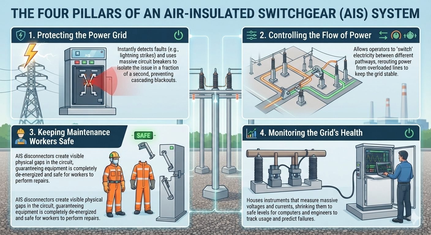
The system performs four core functions to maintain grid stability:
- Fault Protection: When a fault is detected by protective relays, the high-voltage circuit breakers trip within 3 to 5 cycles (50 to 80 milliseconds) to isolate the faulted zone.
- Power Flow Control: Disconnect switches allow operators to safely reroute power during maintenance or load-shedding events.
- Worker Safety: The physical air gap created by an open disconnect switch provides visual confirmation that the circuit is de-energized.
- Grid Monitoring: Instrument transformers (CTs and VTs) continuously step down high currents and voltages to feed real-time data to SCADA systems.
In my experience, failing to verify that the upstream circuit breaker is open before operating a manual disconnect switch is one of the most common causes of substation accidents. Modern facilities utilize mechanical and electrical key interlocks (such as Kirk keys) to physically prevent this dangerous sequence of operations.
Evaluating Air Insulated Switchgear Pros and Cons
Air Insulated Switchgear Trade-offs: Selecting this technology requires balancing low initial capital expenditure and ease of maintenance against larger physical footprint requirements. These systems are highly reliable but remain susceptible to environmental contamination.
When deciding between air-insulated and gas-insulated options, engineers must weigh several competing factors. The choice is rarely simple and depends heavily on the specific project site, environmental conditions, and long-term operational budgets. Below is a detailed breakdown of the primary advantages and disadvantages of utilizing air-insulated configurations in modern power grids.
Key Advantages
- Lower initial capital expenditure due to simpler manufacturing and materials.
- Straightforward visual inspection of all primary contacts and conductors.
- Elimination of environmental risks associated with SF6 gas leaks.
- Simplified maintenance procedures that do not require specialized gas-handling equipment.
- Ease of physical expansion and modification as grid demands grow over time.
Key Disadvantages
- Significantly larger physical footprint required to maintain safe air clearances.
- High susceptibility to environmental pollutants, dust, and wildlife intrusion.
- Increased frequency of routine cleaning to prevent tracking and flashovers.
- Exposed live parts require extensive safety fencing and security measures.
- Accelerated atmospheric corrosion of copper and aluminum busbars in coastal areas.
In my experience, the environmental aspect is becoming a major driver in decision-making. As global regulations tighten around greenhouse gases, the SF6-free nature of air-insulated systems makes them highly attractive for companies aiming to meet strict sustainability targets. However, if your project is located in a dense urban area where land costs are astronomical, the large footprint of an air-insulated substation may make it economically unfeasible.
The simplicity of maintaining these systems cannot be overstated. When a component fails in an air-insulated bay, it can typically be replaced within hours using standard utility tools. In contrast, a failure inside a gas-insulated chamber often requires days of gas evacuation, specialized technicians, and extensive testing before re-energization.
Where Air Insulated Switchgear is Deployed
Air Insulated Switchgear Applications: These systems are deployed across diverse industrial and utility environments where space constraints are secondary to cost and accessibility. They serve as critical nodes in power transmission, heavy manufacturing, and renewable energy integration.
The versatility of air-insulated designs makes them suitable for a wide range of industrial and utility applications. Wherever reliable power distribution is required and physical space is available, these systems are often the default choice for electrical engineers. Below are the primary sectors where these systems are actively deployed to manage high-voltage power distribution.
Utility Transmission and Distribution Substations
In utility networks, these systems serve as the primary nodes for stepping down transmission voltages to distribution levels. Their open layout allows utility operators to quickly identify physical faults, perform routine maintenance, and expand the substation capacity by adding new bays as local power demand increases.
Heavy Industrial Manufacturing Facilities
Large industrial plants, such as steel mills, chemical refineries, and paper mills, require massive amounts of continuous power. Air-insulated systems are installed in dedicated outdoor yards or large indoor vaults to distribute power to heavy machinery, arc furnaces, and large motor control centers safely and reliably.
Renewable Energy Generation Sites
Wind and solar farms utilize these systems at their collector substations to pool the power generated by individual turbines or solar arrays. The switchgear steps up the voltage for injection into the main utility grid, providing a robust point of common coupling that complies with grid-code requirements.
Railway Electrification Networks
Electric rail systems rely on dedicated traction substations to power overhead catenary lines. Air-insulated configurations are commonly used here due to their ability to handle frequent switching operations and the highly dynamic load profiles characteristic of heavy rail transit.
Air-Insulated Switchgear Parameters: Atmospheric air acts as the primary dielectric medium, requiring strict physical clearance boundaries defined by IEC 62271-100 and IEEE C37.20.2 to prevent flashovers across open air gaps.
In my field experience across transmission yards, sizing busbar centers and phase-to-earth distances depends directly on the Basic Impulse Insulation Level (BIL) and short-circuit withstand duration. The matrix below outlines standardized electrical design parameters across common primary grid distribution and transmission voltage tiers.
| Rated Voltage Class (kV) | Impulse Withstand / BIL (kV Peak) | Short-Time Withstand Icw (kA / 3s) | Min Phase-to-Phase Distance (mm) | Min Phase-to-Earth Distance (mm) | Personnel Safety Distance (m) |
|---|---|---|---|---|---|
| 12 kV | 75 kV | 25 kA / 31.5 kA | 120 mm | 120 mm | 2.6 m |
| 36 kV | 170 kV | 31.5 kA / 40 kA | 320 mm | 320 mm | 2.9 m |
| 72.5 kV | 325 kV | 40 kA | 630 mm | 630 mm | 3.2 m |
| 145 kV | 650 kV | 40 kA / 50 kA | 1270 mm | 1200 mm | 4.1 m |
| 245 kV | 1050 kV | 50 kA | 2100 mm | 1900 mm | 5.0 m |
Site elevation requires clear mathematical adjustments. For installations exceeding 1,000 meters above sea level, air density decreases, reducing dielectric strength by roughly 1% per 100 meters of additional elevation. Standard insulation distances must be scaled upward using correction factors from IEC 62271-1 to prevent localized ionization under high ambient humidity.
Switchgear Subsystem Architecture: Air-insulated bays integrate six primary functional subsystems that coordinate fault clearing, power isolation, safety grounding, and telemetry monitoring.
The specification matrix below highlights key engineering components alongside their failure modes and continuous diagnostic metrics, following guidelines established in IEEE C37.20.2 standards for medium and high voltage installations.
| Core Subsystem | Primary Function | Governing Code | Critical Metric | Dominant Failure Mode | Diagnostic Tool |
|---|---|---|---|---|---|
| Circuit Breaker | Fault Interruption & Trip | IEC 62271-100 | Interrupting Time (<40 ms) | Arcing Chamber Erosion | Dynamic Contact Timing |
| Air Disconnector | Visible Circuit Isolation | IEC 62271-102 | Contact Resistance (<50 µΩ) | Jaw Oxidation / Binding | Infrared Thermography |
| Earthing Switch | Trapped Charge Grounding | IEC 62271-102 | Short-Circuit Making Cap | Linkage Alignment Drift | Mechanical Interlock Test |
| Current Transformer | Current Scaling for Relays | IEC 61869-2 | Accuracy Class (5P20 / 0.2S) | Core Saturation / Open CT | Excitation Curve Test |
| Voltage Transformer | Voltage Measurement | IEC 61869-3 | Ratio Error (<0.2%) | Winding Insulation Breakdown | Dissipation Factor (Tan δ) |
| Surge Arrester | Overvoltage Discharge | IEC 60099-4 | Continuous Operating Volt | Varistor Thermal Runaway | Leakage Current Monitor |
Proper mapping of these failure mechanisms allows grid operations to transition from time-based maintenance intervals to condition-based predictive overhauls. Integrating SCADA continuous diagnostic feeds directly reduces forced outage rates in legacy outdoor switchyards.
Field Verification Audit: Commissioning protocols demand systematic insulation verification, mechanical alignment checks, and relay calibration before energizing high-voltage switchgear bays.
I developed this field checklist over decades of commissioning sub-stations to prevent equipment damage and safeguard site technicians. Completing these checks verifies compliance with IEEE C37.20.2 before closing primary bay disconnectors.
Primary Substation Pre-Energization Verification Steps
Never bypass mechanical interlocks or skip primary injection tests during field commissioning. Documenting baseline micro-ohm readings and insulation values creates a vital benchmark for future predictive thermal imaging and contact maintenance.
Field Case Study: Real-World Application
An industrial regional substation suffered recurring thermal lockouts and localized flashovers on its 138 kV Air-Insulated Switchgear line bay, threatening plant grid reliability.
- Severe environmental pollution combined with coastal salt spray led to tracking currents across support post insulators.
- High-contact resistance inside manual disconnector jaw assemblies caused local overheating up to 140°C during peak load transfers.
- Mechanical linkage misalignment prevented disconnector blades from establishing full visible contact, generating localized micro-arcing.
- Protective relays tripped secondary feeder breakers unnecessarily due to corrupted analog CT current signals caused by high ground loop impedance.
By executing a targeted overhaul protocol adhering to IEC 62271-102 standards, site engineers restored dielectric margins and eliminated forced outages.
- Replaced degraded copper disconnector jaws with silver-plated contact fingers, reducing joint resistance from 180 µΩ to 28 µΩ.
- Applied hydrophobic silicone rubber coatings to porcelain post insulators, increasing creepage distance resistance and halting leakage currents.
- Installed motorized disconnector drives with optical position sensors, transmitting definitive open/closed telemetry to SCADA.
- Re-grounded current transformer secondary neutral points to a single substation copper ground grid point, restoring signal integrity.
This field rehabilitation project highlights why physical contact maintenance and clear visible air gaps remain foundational to power system integrity. Routine infrared thermal scans combined with automated micro-ohm contact resistance testing prevent high-resistance thermal failures before they escalate into phase-to-phase busbar outages.
Frequently Asked Engineering Questions
How does air-insulated switchgear ensure operator safety during substation maintenance?
Air-insulated switchgear provides a physical, visible air gap that guarantees complete circuit isolation before maintenance teams begin working on high-voltage equipment.
- Visible isolation: Disconnect switches physically separate contacts to visually confirm a de-energized state.
- Safety grounding: Integrated grounding switches discharge residual capacitive charges safely to the earth.
- Mechanical interlocks: Prevent accidental operation of disconnectors while the circuit breaker is closed per IEEE C37.20.2.
What are the primary differences between IEC 62271 and IEEE C37.20.2 for AIS?
While both standards govern high-voltage switchgear design, they differ in testing methodologies, structural classifications, and regional application parameters.
- Voltage ratings: IEC 62271 uses metric-based system voltages, whereas IEEE C37.20.2 focuses on nominal North American voltage classes.
- Enclosure testing: IEEE defines specific metal-clad and metal-enclosed parameters, while IEC uses internal arc classification (IAC) ratings.
- Temperature rise limits: The standards specify different allowable temperature rises for contacts and busbars under continuous rated current.
How does an AIS system protect the power grid from transient faults?
Air-insulated switchgear isolates transient faults rapidly to prevent localized grid issues from cascading into widespread regional blackouts.
- Fault detection: Instrument transformers continuously monitor current and voltage levels, sending real-time data to protective relays.
- Rapid arc interruption: High-voltage circuit breakers trip within milliseconds, using sulfur hexafluoride (SF6) or vacuum interrupters to extinguish the arc.
- Automatic reclosing: Overhead line breakers attempt to restore power after transient lightning strikes clear.
Why is regular environmental monitoring necessary for air-insulated switchgear installations?
Because AIS relies on ambient air as the primary dielectric medium, environmental factors directly impact its insulation performance and overall reliability.
- Humidity and condensation: High moisture levels reduce the dielectric strength of air, increasing flashover risks.
- Particulate pollution: Dust, salt, and industrial emissions deposit on insulator surfaces, creating conductive tracking paths.
- Temperature fluctuations: Extreme thermal cycles cause expansion and contraction, potentially loosening critical busbar connections.
What role does instrumentation play in SCADA integration for AIS substations?
Modern instrumentation transforms physical grid parameters into actionable digital data for real-time SCADA monitoring, control, and predictive maintenance.
- Continuous telemetry: Current and voltage transformers feed precise analog measurements to remote terminal units (RTUs).
- Condition monitoring: Thermal sensors and partial discharge detectors track equipment health to predict insulation failures.
- Remote control execution: SCADA systems send open or close commands to motorized disconnectors and circuit breakers instantly.
Complete Course on
Piping Engineering
Check Now
Key Features
- 125+ Hours Content
- 500+ Recorded Lectures
- 20+ Years Exp.
- Lifetime Access
Coverage
- Codes & Standards
- Layouts & Design
- Material Eng.
- Stress Analysis
