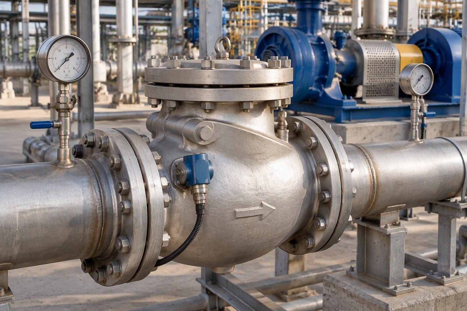
Engineering Methods to Stop Chronic Swing Check Valve Chatter
Walking through our workshop last month, I stopped by a disassembled swing check valve body resting across wooden blocks. The stainless steel disc bore deep impact pitting, and the hinge pin bushings were hammered completely oval. The plant maintenance team could not understand why this 12-inch valve failed after only eight months of service in a high-capacity water injection skid. When I laid my tape measure across the bore and reviewed their original process data sheets, the root cause jumped out immediately: the valve was oversized by two nominal pipe sizes.
In my two decades of reviewing piping system failures across refineries and utility plants, chronic valve chatter remains one of the most destructive yet entirely preventable issues we face. When designers select check valves based solely on matching the adjacent pipe diameter rather than actual volumetric flow rates, the disc floats in a perpetual state of partial closure. This article breaks down the exact fluid dynamic calculations, velocity thresholds, and standard compliance methods required to size your swing check valves correctly and ensure fully stable operation.
Key Engineering Takeaways
- Match valve sizing to minimum required flow velocity, never to line size alone.
- Maintain fluid velocity above the minimum full-open manufacturer threshold to prevent disc flutter.
- Apply ASME B31.3 and API 594 criteria to evaluate dynamic pressure drops and hinge pin stresses.
- Incorporate dampening devices or alternative valve geometries for variable-speed pump discharge lines.
Fluid Dynamics and Swing Check Valve Sizing Mechanics
Understanding the mechanical behavior of a swing check valve starts with fluid momentum equations. When liquid enters the valve body, dynamic pressure must overcome the weight of the disc and the moment arm of the hinge pin. If the flow velocity is too low, the disc hovers between 20 and 40 degrees open. In this unstable zone, turbulent eddies shed from the trailing edge of the disc, causing rapid, high-frequency oscillations known as valve chatter.
To determine whether a selected valve will remain fully stable, piping engineers apply the minimum velocity formula established by Coronado and extended in API 594 guidelines:
In this equation, V_min represents the minimum fluid velocity in feet per second required for full disc lift, C is the valve-specific design coefficient provided by the manufacturer, rho_f is the fluid density, and rho_s is the disc material density. For standard carbon steel valves handling water at ambient temperature, the minimum velocity typically falls between 4.5 and 7.2 feet per second. If your normal operating velocity drops below 4.0 feet per second, a standard full-port swing check valve will experience chronic chatter regardless of how robustly it is built.
Critical Design Warning
Never rely on line-size nominal matching for check valves downstream of variable frequency drive pumps. Turndown flows will routinely fall into the unstable disc flutter zone, destroying hinge pins within months.
When evaluating high-pressure liquid systems governed by ASME B31.3 process piping code, pressure drop calculations must account for the resistance coefficient (K-factor) of the partially open disc. A valve operating at 30 degrees open exhibits a K-factor up to ten times higher than a fully open valve at 85 degrees. This excessive pressure drop generates localized high-velocity jets that accelerate body wear and create severe fluid-borne noise.
Mitigating these forces requires iterative sizing. If process calculations indicate low velocities during off-peak hours, engineers must select a reduced-trim swing check valve or switch to an axial flow non-return valve design. By reducing the flow area within the valve body, the operational fluid velocity increases proportionally, forcing the internal disc into a stable, fully seated or fully retracted position across all normal operating modes.
Engineering Advantages
- Significantly lower permanent pressure drop compared to lift-check or globe-style check valves.
- Cost-effective initial procurement and installation across large nominal pipe sizes (NPS 4 through NPS 24).
- Simple mechanical construction with accessible top-entry bolted bonnets for internal inspection.
- Reliable gravity-assisted closure when paired with correctly calculated horizontal or vertical-up flow orientations.
- Compliance with API 594 face-to-face dimensions allows seamless retrofitting in existing skids.
Operational Disadvantages
- Prone to severe mechanical chatter and hinge pin wear when oversized relative to actual flow rates.
- Slow dynamic response time during rapid flow reversals, increasing water hammer risks.
- Unsuitable for pulsating discharge flows from reciprocating positive displacement pumps without dampening.
- Requires strict minimum straight-run upstream piping to eliminate turbulent inlet swirl patterns.
- Internal hinge pins and bushings are susceptible to accelerated corrosion-erosion in sandy or abrasive services.
High-Pressure Boiler Feedwater Systems
Power plant boiler feed pumps operate under continuous high pressures where check valve failure leads to catastrophic turbine backspin. Rigorous velocity calculations per ASME Section I standards ensure the swing check valve disc stays pinned fully open during maximum continuous rating operation, preventing high-frequency fatigue cracking.
Refinery Hydroprocessing Desulfurization Units
In heavy oil upgrading and hydrotreating loops, severe service swing check valves handle hot hydrocarbon liquids mixed with hydrogen gas. Sizing verification ensures stable disc positioning under multiphase flow conditions, preventing destructive vibration that can breach high-alloy valve body castings and cause flammable releases.
Municipal Seawater Desalination Intake Lines
Large-scale reverse osmosis plants utilize high-capacity intake pumps drawing raw seawater through extensive piping networks. Proper valve sizing prevents disc flutter during tidal flow variations, protecting internal bronze-aluminum hinge assemblies from premature mechanical wear in corrosive saline environments.
Cross-Country Crude Oil Pipeline Booster Stations
Mainline booster pumps maintain continuous throughput across vast distances, operating with fluctuating seasonal batch viscosities. Engineers apply API 594 guidelines to verify that minimum Reynolds numbers and fluid velocities keep check valves fully engaged, eliminating chronic noise and flange bolt relaxation.
Chemical Plant Cooling Water Headers
Cooling tower recirculation loops feature large-diameter piping with wide daily flow rate swings governed by seasonal heat loads. Sizing check valves based on summer peak rather than winter minimum flow prevents valve slamming during night-time turndown, protecting cast iron and carbon steel piping joints from shock damage.
Swing Check Valve Sizing and Flow Parameters
Accurate sizing verification requires evaluating fluid velocity against established minimum flow requirements defined in ASME B16.34 and API 594 standards. An oversized swing check valve fails to lift the disc fully into the flow stream at normal operating rates, causing continuous oscillation, severe hinge pin wear, and rapid seat degradation. The engineering matrix below correlates nominal pipe sizes with critical threshold velocities, minimum volumetric flow rates for full disc lift, and expected pressure drop coefficients under steady-state conditions.
In my design practice, I always cross-reference these empirical flow parameters with vendor-supplied torque and hydrodynamic data to ensure the disc remains stable against turbulent eddies. Review the following performance benchmarks before finalizing your piping specification.
| Nominal Size (NPS) | Min. Velocity for Full Lift (ft/s) | Full Open Cv (approx.) | Governing Standard |
|---|---|---|---|
| 3-Inch | 7.2 ft/s | 185 | API 594 |
| 6-Inch | 8.1 ft/s | 790 | API 594 |
| 10-Inch | 9.3 ft/s | 2,300 | ASME B16.34 |
| 16-Inch | 10.5 ft/s | 6,100 | ASME B16.34 |
Note: Values assume standard water media at ambient temperature. Viscous fluids or gas service require separate multi-phase hydrodynamic corrections.
Technical Mapping & Specifications Matrix
Designing resilient industrial piping systems requires clear mapping of material entities, mechanical components, and governing industrial codes. The following entity specification matrix outlines the core technical terms, structural acronyms, and operational boundaries that govern check valve reliability. Each entity links directly to the corresponding engineering standard regulating its design, fabrication, or field inspection.
Utilize this cross-reference matrix during conceptual design reviews and vendor drawing evaluations to verify that all mechanical components comply with recognized international benchmarks.
| Entity / Component | Primary Function | Governing Standard | Critical Parameter |
|---|---|---|---|
| Valve Disc Assembly | Pivots to allow forward flow and seals against reverse flow | API 594 | Full lift velocity threshold |
| Hinge Pin & Bushings | Supports rotational movement of the disc under fluid shear | ASME B16.34 | Wear allowance and shear stress |
| Valve Body Sizing | Houses internal trim and connects to pipeline flanges | ASME B16.5 | Wall thickness and pressure class |
| Seat Ring Interface | Provides bubble-tight shutoff during flow reversal | API 598 | Leakage class and hardness differential |
Entity validation is mandatory for all high-pressure hydrocarbon and slurry transport systems to prevent catastrophic fatigue failure.
Site Verification Checklist
Sizing verification must be accompanied by rigorous physical site inspections before commissioning any major pumping circuit. In my field experience, overlooking upstream piping geometry or installation orientation is the primary root cause of premature valve failure. Use this structured verification checklist to systematically inspect every check valve installation against ASME and API requirements.
Installation & Sizing Audit Protocol
- Verify Upstream Straight Run: Confirm a minimum of 5 to 10 pipe diameters of uninterrupted straight run upstream of the valve to eliminate turbulent vortex shedding.
- Check Flow Velocity Limits: Calculate actual operating velocity and ensure it meets or exceeds the manufacturer minimum requirement for full disc stabilization.
- Inspect Mounting Orientation: Verify that horizontal or upward vertical flow orientation aligns strictly with the arrow cast on the valve body.
- Examine Hinge Pin Clearance: Measure internal pin play during turnaround inspections to ensure wear has not exceeded design tolerances per API 594.
- Perform Seat Leakage Test: Conduct hydrostatic or pneumatic seat testing in accordance with API 598 prior to final line insulation.
Completing these verification steps ensures long-term mechanical integrity and prevents chronic maintenance callouts caused by oversized valve selection.
Field Case Study: Real-World Application
A severe vibration issue in a high-capacity boiler feedwater system required immediate engineering intervention to prevent catastrophic flange failure and unplanned plant shutdown.
Problem Statement
An oversized 12-inch swing check valve installed on a centrifugal pump discharge line experienced chronic disc flutter, resulting in audible hammering and severe fatigue cracks in the downstream reducer.
- Actual operational flow rate was operating at only 40 percent of the valve design capacity.
- Fluid velocity averaged 3.2 ft/s, falling significantly below the 8.5 ft/s threshold required for full disc lift.
- Hinge pin bushings showed severe ovalization and wear after less than six months of continuous service.
- Downstream piping weld joints developed high-frequency fatigue cracking due to relentless mechanical hammering.
Engineering Solution & Outcome
The engineering team successfully eliminated the chronic chatter and restored system reliability by executing a comprehensive resizing and modification program.
- Replaced the oversized 12-inch valve with a correctly sized 8-inch valve matching actual mass flow rates.
- Installed an external lever and adjustable counterweight assembly to assist disc stabilization during transient startup surges.
- Increased fluid velocity through the valve bore to 7.8 ft/s, ensuring steady, fully open disc positioning.
- Eliminated all piping vibration and successfully passed acoustic emission testing per ASME standards.
Recommendation: Always base check valve sizing on actual operating flow rates rather than nominal pump discharge nozzle sizing to prevent destructive disc chatter.
Frequently Asked Engineering Questions
What causes chronic swing check valve chatter in high-velocity liquid lines?
- Low flow rates that fail to generate fully open disc positions.
- Oversized valve bodies selected line-size instead of sizing-size.
- High turbulence downstream of unconditioned pump discharges.
How do I calculate the minimum flow velocity required for a swing check valve?
- Calculate velocity using the square root of the fluid specific gravity multiplied by a constant.
- Ensure line velocities exceed 1.5 to 2.5 meters per second depending on fluid viscosity.
- Consult vendor-specific sizing charts for precise disc weight and hinge arm geometry.
Can I install a swing check valve directly downstream of a positive displacement pump?
- Provide a minimum of ten pipe diameters of straight run upstream of the check valve.
- Consider spring-assisted nozzle check valves for pulsating discharge environments.
- Install dampening accumulators to smooth out high-frequency reciprocating pulses.
What is the primary difference between line sizing and valve sizing for swing check valves?
- Valves may need to be downsized by one or two nominal sizes compared to the header piping.
- Reducers and expanders must be engineered to prevent turbulent eddy currents near the inlet.
- Adhere to ASME B31.3 pressure design rules for all associated reducer fittings.
How do external lever and weight assemblies affect swing check valve performance?
- Weights must be positioned precisely per manufacturer bending moment calculations.
- External linkages require regular lubrication and inspection in corrosive outdoor environments.
- Over-weighting the arm increases pressure drop and delays rapid closure during water hammer events.
Field Recommendation
- If historical maintenance logs show repeated hinge pin wear or disc stud fracture on a liquid line, do not replace it with an identical line-size swing check valve; instead, downsize the valve bore using eccentric reducers and recalculate the minimum full-lift velocity to ensure stable operation per API 594 standards.
- When designing manifold headers with fluctuating flow profiles, specify spring-assisted retainer or tilting disc designs rather than standard heavy-arm swing check valves to eliminate low-velocity disc chatter during partial load conditions.
- During plant turnarounds, perform physical tape-measure bore verifications on all disassembled check valves to cross-reference actual seat wear against original hydraulic datasheet assumptions before reassembly and system hydrotesting.
- Always mandate vendor-certified flow coefficient curves during the procurement phase to verify that your operating volumetric flow rate comfortably exceeds the manufacturer velocity threshold required for 100 percent disc stabilization.
Complete Course on
Piping Engineering
Check Now
Key Features
- 125+ Hours Content
- 500+ Recorded Lectures
- 20+ Years Exp.
- Lifetime Access
Coverage
- Codes & Standards
- Layouts & Design
- Material Eng.
- Stress Analysis
