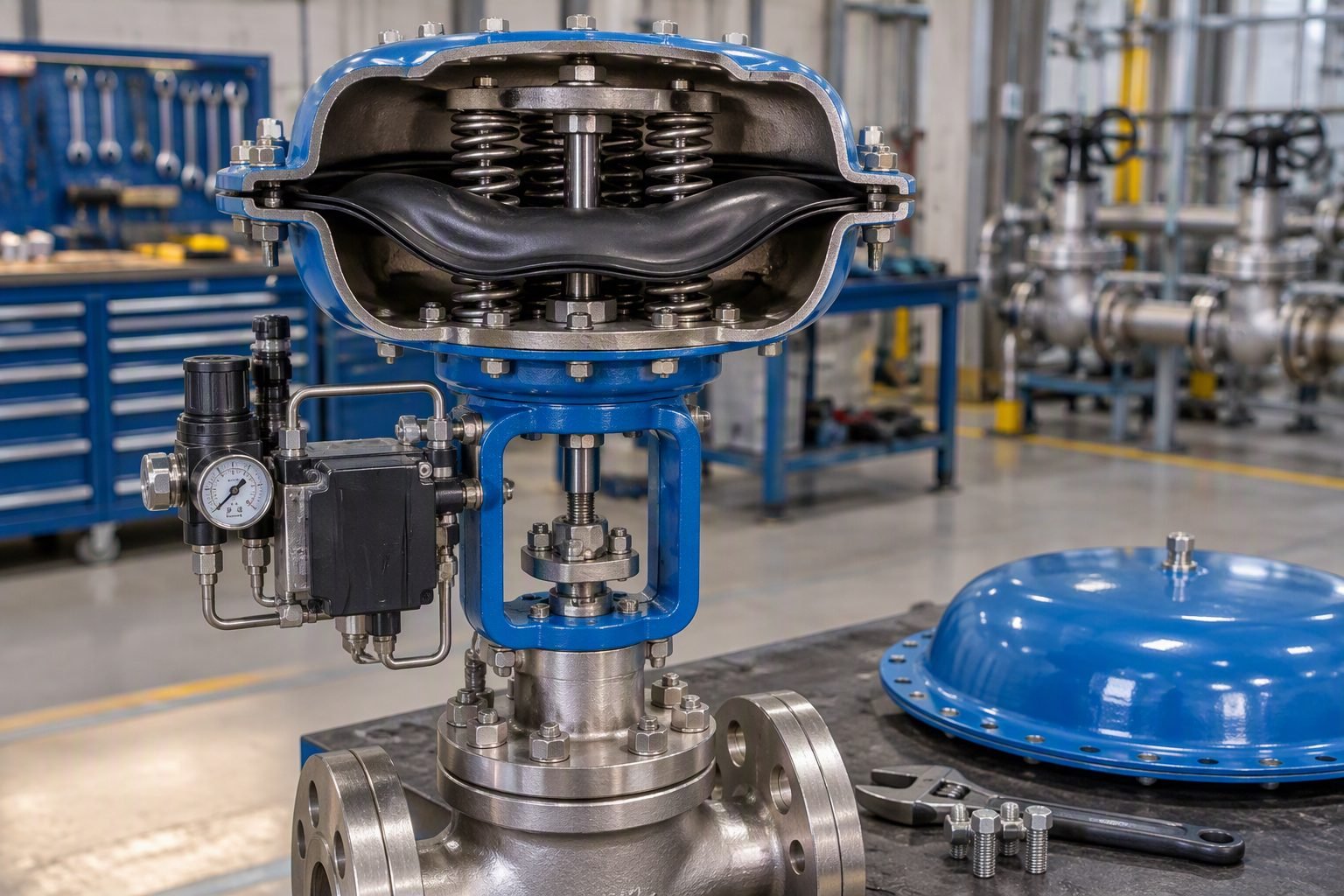
Diagnosing Check Valve Slam and Chatter with Vibration Monitoring
In my twenty years managing critical high-pressure pumping stations, I have witnessed the destructive power of unchecked valve dynamics firsthand. When a high-capacity centrifugal pump trips or ramps down rapidly, the fluid column reverses momentum within milliseconds. If the check valve disk cannot close fast enough to intercept this reversal, it slams violently against the seat. This phenomenon, known as check valve slam, generates instantaneous pressure spikes that can shatter pipe elbows, rupture pump casings, and fracture valve bodies.
Mitigating this destructive behavior requires moving beyond reactive maintenance and embracing advanced diagnostic monitoring. By mounting high-frequency accelerometers directly onto the valve body and pairing them with precision downstream pressure gauges, operations teams can capture the distinct acoustic and vibrational signatures of both slam and chatter. This data-driven approach allows engineers to apply ASME OM-2015 operational standards, select appropriate spring-assisted closure mechanisms, and protect critical infrastructure before fatigue leads to containment failure.
Key Engineering Takeaways
- Differentiate Frequencies: High-frequency impacts indicate severe slam, whereas continuous medium-frequency oscillations point toward unstable disk chatter.
- Standard Compliance: Utilize ASME OM-2015 guidelines for inservice monitoring of dynamic check valve degradation.
- Sensor Placement: Mount vibration sensors on the downstream hinge pin axis to capture maximum radial and axial acceleration vectors.
Engineering Mechanics of Check Valve Slam
Valve Slam Mechanics: Check valve slam occurs when the reverse velocity of the fluid column exceeds the dynamic closing capability of the closure element, leading to severe water hammer phenomena as defined by ASME B31.3 piping codes. Understanding the exact transition phase between forward flow deceleration and flow reversal is critical for piping design engineers.
When a pump trips, forward velocity drops rapidly. The deceleration rate (-(dv/dt)) dictates the time window available for the valve disk to travel from the full-open position to the fully seated position. If the fluid deceleration outpaces the disk closing time—influenced by disk weight, buoyant forces, and spring constant—the disk remains partially open when flow reversal initiates.
The resulting reverse velocity builds rapidly until the disk is forcibly dragged into the seat by the backward-flowing water column. This abrupt deceleration of the reversed fluid mass creates an instantaneous pressure wave governed by the Joukowsky equation:
Where Delta P represents the peak pressure surge, rho is fluid density, c is acoustic velocity in the piping medium, and Delta v is the sudden change in velocity. In rigid steel pipes handling water, acoustic velocities exceed 1,200 meters per second, meaning even a minor unchecked velocity change can produce pressure spikes exceeding several megapascals.
Distinguishing Slam from Chatter via Vibration Signatures
Vibration analysis provides the most reliable diagnostic window into check valve internal behavior without requiring intrusive teardowns. However, engineers must correctly differentiate between transient slam and continuous valve chatter, as their root causes and spectral signatures are entirely distinct.
Valve chatter occurs when a swing check valve operates in a partially open position under low flow velocities or turbulent pump discharge streams. The disk hovers unsteadily against the upper stop or floats in the fluid stream, rapidly oscillating back and forth. This constant fluttering produces a continuous, broadband high-frequency vibration signature combined with discrete impacting frequencies matching the disk’s natural mechanical frequency.
Vibration Spectrum Characteristics
- Chatter Signature: High continuous spectral energy between 500 Hz and 5,000 Hz, showing random impacts and modulation from pump vane pass frequencies.
- Slam Signature: Transient, high-amplitude impulse waveforms (shock pulses) accompanied by low-frequency piping ring frequencies (10 Hz to 100 Hz).
- Background Noise: Hydraulic turbulence creates smooth broadband noise below 300 Hz, easily separated from mechanical impact spikes using envelope analysis.
Applying ASME OM-2015 Standards for Inservice Monitoring
The ASME OM-2015 standard (Operation and Maintenance of Nuclear Power Plants, specifically Mandatory Appendix I and related subsections) outlines rigorous testing and monitoring criteria for pressure relief and check valves. Although originating in nuclear safety applications, these guidelines have become the gold standard for high-consequence chemical, petrochemical, and municipal water transmission systems.
Under ASME OM-2015, diagnostic monitoring must establish a baseline vibration profile under normal operating flow rates. Plant engineers track peak overall vibration velocity (in inches per second or millimeters per second RMS) alongside high-frequency peak-to-peak acceleration (g-pk). When vibration levels exceed 2.5 times the baseline or when discrete impact harmonics appear in the spectrum, maintenance action is triggered.
Critical Warning: Hinge Pin Fatigue and Internal Separation
Unmitigated check valve chatter induces rapid cyclical stress reversal on internal hinge pins, bushings, and disk studs. Prolonged operation in a chattering state leads to accelerated wear of pivot pins, causing the disk to misalign, wedge sideways, or detach entirely. A detached disk acts as an uncontrolled downstream blockage or travels into pump impellers, causing catastrophic mechanical failure. Inspect hinge pin wear tolerances strictly in accordance with ASME B16.34 manufacturing guidelines.
Engineering Solutions for Slam and Chatter Elimination
Once diagnostic vibration monitoring confirms the presence of slam or chatter, piping engineers must implement corrective design modifications. Adjusting pump ramp-down times via variable frequency drives (VFDs) is often the most effective first step, extending deceleration times beyond the critical closing threshold of the valve.
When operational adjustments are insufficient, hardware modifications are mandatory. Replacing conventional heavy swing check valves with spring-assisted nozzle check valves or dual-plate wafer check valves drastically reduces closing times. Spring-assisted designs store mechanical energy during forward flow, forcing the closure disk forward before flow reversal can occur. Furthermore, sizing the check valve strictly based on actual operational flow velocity—rather than matching adjacent pipe diameter—ensures the valve achieves full lift during normal operation, eliminating partial-stroke flutter and destructive chatter.
Implementing real-time vibration diagnostics and advanced mechanical mitigation for check valve slam provides substantial operational benefits, though it also introduces specific engineering and maintenance complexities that must be managed carefully.
Advantages
- Early Failure Detection: Identifies internal hinge wear and disk flutter long before catastrophic mechanical breakdown occurs.
- Asset Protection: Prevents destructive water hammer pressure spikes, preserving downstream piping elbows, flanges, and pump casings.
- Compliance Alignment: Satisfies ASME OM-2015 inservice testing mandates for critical industrial fluid systems.
- Data-Driven Sizing: Provides empirical flow and vibration data to optimize future valve sizing and eliminate partial-stroke operation.
- Downtime Reduction: Replaces reactive emergency repairs with planned, condition-based maintenance schedules.
Disadvantages
- High Initial Capital Outlay: Requires investment in high-frequency accelerometers, continuous data loggers, and telemetry integration.
- Signal Interpretation Complexity: Distinguishing valve impacting frequencies from background pump cavitations requires specialized vibration analysis expertise.
- Sensor Mount Vulnerability: Harsh industrial environments and high ambient temperatures can degrade externally mounted accelerometers and cabling.
- Maintenance Overhead: Routine calibration and sensor health checks add to the facility inservice inspection workload.
- Retrofit Space Constraints: Installing upgraded spring-assisted nozzle check valves often requires modifying existing pipe spool lengths.
Vibration-based diagnostic monitoring and advanced check valve selection are deployed across diverse heavy industries where fluid transient control is paramount to safety and continuous production.
High-Pressure Boiler Feedwater Systems
Boiler feedwater pumps operate at extreme pressures and temperatures, feeding high-purity water directly into steam generators. Sudden pump trips in these circuits generate severe reverse flow dynamics capable of destroying multi-stage pump internals. Implementing accelerometer monitoring combined with spring-assisted nozzle check valves ensures immediate, shock-free closure, protecting high-value turbomachinery and maintaining continuous steam generation.
Municipal Water Transmission Booster Stations
Large municipal booster stations utilize high-capacity horizontal split-case pumps to push potable water across extensive cross-country pipeline networks. Electrical grid fluctuations frequently cause sudden pump shutdowns, triggering dangerous water hammer waves. Water authorities utilize real-time vibration diagnostics to monitor large swing check valves, scheduling overhauls before hinge pin wear leads to catastrophic pipeline rupture.
Petrochemical Hydroprocessing Charge Pumps
Refinery hydrotreaters and hydrocrackers rely on reciprocating and heavy centrifugal charge pumps handling hazardous, flammable hydrocarbon liquids at elevated temperatures. In these aggressive environments, check valve chatter accelerates fatigue cracking in alloy steel piping welds. Continuous vibration tracking ensures compliance with strict ASME OM-2015 integrity standards, preventing loss-of-containment incidents.
Desalination High-Pressure Reverse Osmosis Racks
Reverse osmosis desalination trains utilize high-pressure positive displacement and centrifugal pumps to overcome osmotic pressure across membrane assemblies. Rapid valving actions and variable recovery rates frequently induce localized fluid oscillations and valve flutter. Deploying high-frequency vibration sensors downstream of check valves allows operators to detect early disk instability and optimize membrane protection protocols.
Engineering Parameters for Check Valve Slam Diagnostics
Diagnosing severe fluid transients and valve disk dynamics requires precise cross-referencing of operating velocities, acoustic wave speeds, and reverse flow velocities against established industry standards. In my plant troubleshooting assignments, evaluating these specific mechanical thresholds prevents catastrophic seat erosion, hinge pin shear, and downstream piping rupture.
The following engineering data table aggregates critical operating limits and diagnostic boundaries governed by ASME OM-2015 and API 594 specifications. Use these reference values during surge analysis, baseline vibration benchmarking, and routine preventive maintenance inspections.
| Parameter Description | Normal Operating Limit | Slam/Chatter Threshold | Governing Standard |
|---|---|---|---|
| Mean Flow Velocity | 1.5 m/s to 3.0 m/s | < 1.0 m/s (Low Velocity Instability) | ASME OM-2015 |
| Valve Deceleration Rate | < 5 m/s squared | > 20 m/s squared (Rapid Reversal) | API 594 |
| Peak Reverse Velocity | Zero (Tight Seating) | > 0.5 m/s prior to disk contact | ASME B16.34 |
| Vibration Acceleration | < 0.5 g RMS (Broadband) | > 2.5 g RMS (Impact Spike Trains) | ISO 10816-3 |
| Disk Travel Angle | 60 to 85 degrees open | < 30 degrees (Unstable Flutter Zone) | Manufacturer Data |
Note: Exceeding the specified deceleration threshold without assisted closure devices will invariably induce severe hydraulic shock and high-frequency housing vibration.
Technical Mapping & Specifications Matrix
Modern industrial asset management relies on structured data mapping to correlate physical piping phenomena with digital sensor telemetry. When investigating check valve operational anomalies, engineers must align acoustic signatures, structural resonances, and fluid mechanical variables into a coherent diagnostic matrix.
The following matrix establishes the relationship between core structural entities, regulatory codes, and physical parameters observed during field monitoring. This structured mapping ensures that condition-monitoring teams speak a unified technical language when evaluating vibration spectra against design limitations.
| Entity Category | Technical Identifier | Primary Parameter | Reference Standard |
|---|---|---|---|
| Valve Dynamic Entity | Swing Check Disk Assembly | Moment of Inertia / Travel Limit | API 594 |
| Vibration Transducer | Piezoelectric Accelerometer | Peak Acceleration (g) / Frequency (Hz) | ISO 10816-3 |
| Transient Fluid Entity | Water Hammer / Pressure Surge | Joukowsky Pressure Spike (Delta P) | ASME OM-2015 |
| Piping Support Entity | Rigid Clamp / Snubber | Displacement Amplitude (mm) | ASME B31.3 |
| Diagnostic Output | Fast Fourier Transform Spectrum | Harmonic Energy Distribution | ISO 13373-1 |
Synthesizing these entities into automated condition monitoring systems allows plant operators to detect early-stage mechanical fatigue before major component failure occurs.
Site Verification Checklist for Check Valve Diagnostics
Verifying the structural integrity and dynamic stability of check valves in high-pressure pumping stations requires a systematic inspection protocol. Drawing from my field commissioning experience, overlooking minor installation geometry errors or sensor calibration drifts will invalidate diagnostic vibration readings and mask impending mechanical failures.
Execute this comprehensive site verification checklist during commissioning, after major pump overhauls, or when vibration sensors indicate abnormal transient spikes. Ensure all findings are documented in accordance with ASME OM-2015 guidelines.
Checklist Validation Protocol
- Verify Upstream Straight Pipe Length: Ensure a minimum of 5 to 10 pipe diameters of straight unobstructed piping exist between the pump discharge flange and the check valve to eliminate turbulent eddy currents.
- Inspect Accelerometer Mounting Rigidity: Confirm that the vibration sensor is stud-mounted directly to a machined pad on the valve body, avoiding magnetic bases that attenuate high-frequency impact spikes.
- Audit Flow Velocity Profiles: Validate that normal operating flow velocity exceeds the minimum manufacturer threshold (typically 1.5 m/s) to maintain full disk stabilization against the valve stop.
- Check Hinge Pin Wear and Play: Perform manual or borescope inspection of internal hinge pins and bushings to detect excessive clearance that promotes disk flutter and chatter.
- Review Pressure Gauge Dampening: Verify liquid-filled pressure gauges adjacent to the valve are equipped with snubbers to protect bourdon tubes from high-frequency hydraulic hammering.
- Calibrate Baseline Vibration Spectra: Record baseline overall velocity and acceleration spectra under steady-state operating conditions per ISO 10816-3 standards.
- Analyze Pump Trip Response: Simulate or record data during planned pump shutdown transients to verify that check valve closure time prevents reverse velocity spikes.
Adhering strictly to each checkpoint on this list safeguards downstream piping networks and ensures regulatory compliance with plant safety mandates.
Field Case Study: Real-World Application
During a recent plant audit at a high-capacity boiler feed water facility, operations reported intermittent loud metallic banging noises and severe vibration originating near the primary multi-stage centrifugal pump discharge line. Plant engineers suspected severe valve chatter, but initial visual inspections yielded no conclusive evidence of mechanical failure.
Problem Analysis & Contributing Factors:
The installation suffered from severe hydrodynamic instability caused by improper valve sizing and turbulent flow profiles right at the pump outlet.
- Operating flow velocity dropped to 0.8 m/s during partial load conditions, falling well below the manufacturer’s 1.5 m/s minimum stability threshold.
- The heavy swing check valve disk hovered in a partially open, unstable state, resulting in continuous high-frequency chatter against the internal stop.
- The accelerometer mounted on the valve body recorded broadband acceleration spikes exceeding 3.5 g RMS with distinct impact harmonics.
- Proximity pressure gauges displayed violent needle oscillations of plus or minus 1.2 MPa during pump ramp-down phases.
- Lack of adequate straight pipe length upstream of the valve introduced asymmetric swirl directly into the inlet disk assembly.
Outcome & Corrective Actions:
Implementing a targeted retrofit based on ASME OM-2015 guidelines completely eliminated the transient slamming phenomena and restored piping stability.
- Replaced the oversized standard swing check valve with a dual-plate retainerless check valve equipped with heavy-duty internal torsion springs.
- Relocated the vibration accelerometer to a rigid structural gusset welded directly to the main piping spool to improve high-frequency response accuracy.
- Added a 5-diameter flow straightening spool piece immediately downstream of the pump discharge flange to eradicate inlet turbulence.
- Post-modification vibration monitoring confirmed acceleration levels dropped from 3.5 g RMS down to an acceptable 0.35 g RMS baseline.
- Pressure gauge needle oscillation ceased entirely, preventing premature fatigue failure of the bourdon tube mechanisms and flange gaskets.
Recommendation: For similar high-energy pump systems, always perform rigorous dynamic sizing calculations to ensure check valve disks remain fully stabilized across the entire operating flow envelope.
Frequently Asked Engineering Questions
What is the fundamental difference between check valve slam and valve chatter?
- Check Valve Slam: Caused by high reverse velocity during flow reversal, resulting in a single high-energy hydraulic shock.
- Valve Chatter: Caused by operation in a partially open, unstable flow regime near the minimum required velocity, causing rapid disc oscillation.
- Frequency Signature: Slam exhibits a low-frequency transient spike, whereas chatter maintains a continuous high-frequency vibration spectrum.
How do vibration sensors help diagnose check valve degradation before failure?
- Impact Detection: Captures transient shock peaks indicating disc-to-seat slapping during partial load operation.
- Trend Analysis: Tracks RMS acceleration velocity over time to flag progressive hinge pin wear and increased free play.
- Spectral Resolution: Fast Fourier Transform (FFT) analysis separates flow turbulence noise from mechanical chatter frequencies.
What fluid velocity is required to prevent swing check valve chatter?
- Full Lift Velocity: Typically requires liquid velocities between 1.5 to 3.0 m/s depending on fluid density and viscosity.
- Manufacturer Curves: Always cross-reference manufacturer specific velocity requirement charts rather than relying solely on line size sizing.
- Oversized Piping: Avoid installing oversized check valves in reduced piping runs, as this artificially depresses local flow velocity.
How does pump startup and shutdown transient behavior induce check valve slam?
- Deceleration Rate: Deceleration rates exceeding 5 m/s squared require spring-assisted closure or dampening devices.
- Water Hammer Coupling: The sudden flow stoppage generates severe pressure spikes that exceed normal operating pressure ratings.
- ASME B31.3 Compliance: Piping stress analysis must account for these transient peak pressures during support design.
What structural modifications can eliminate persistent check valve chatter in existing plants?
- Spring Assists: Install heavy-duty external torsion springs or internal loading springs to force rapid closure independent of gravity.
- Valve Type Retrofit: Replace conventional swing check valves with nozzle-type axial flow check valves featuring rapid response spring action.
- Upstream Spool Modification: Add flow straightening elements or increase straight run distances to eliminate pump discharge turbulence loops.
Field Recommendation
Based on two decades of resolving piping vibration and water hammer anomalies across heavy process facilities, I advise engineers to make the following decisive judgments when tackling check valve reliability issues:
- If persistent high-frequency vibration is detected on a swing check valve body during normal turndown operation, immediately verify actual fluid velocity against manufacturer full-lift curves rather than assuming line size adequacy.
- If pump trip transient spikes consistently cause severe disc slam, retrofit the piping node with a nozzle-type axial check valve or a spring-assisted disc design to reduce closure time below the critical deceleration threshold.
- If budget constraints prevent immediate valve replacement, install a permanent piezoelectric accelerometer with continuous SCADA trending to monitor RMS acceleration trends and schedule preventive maintenance before hinge pin failure occurs.
- If spatial limitations force check valve installation directly adjacent to pump discharge elbows, insert a minimum of five pipe diameters of straight spool or a flow conditioner to eliminate swirl turbulence and stabilize disc position.
Complete Course on
Piping Engineering
Check Now
Key Features
- 125+ Hours Content
- 500+ Recorded Lectures
- 20+ Years Exp.
- Lifetime Access
Coverage
- Codes & Standards
- Layouts & Design
- Material Eng.
- Stress Analysis
