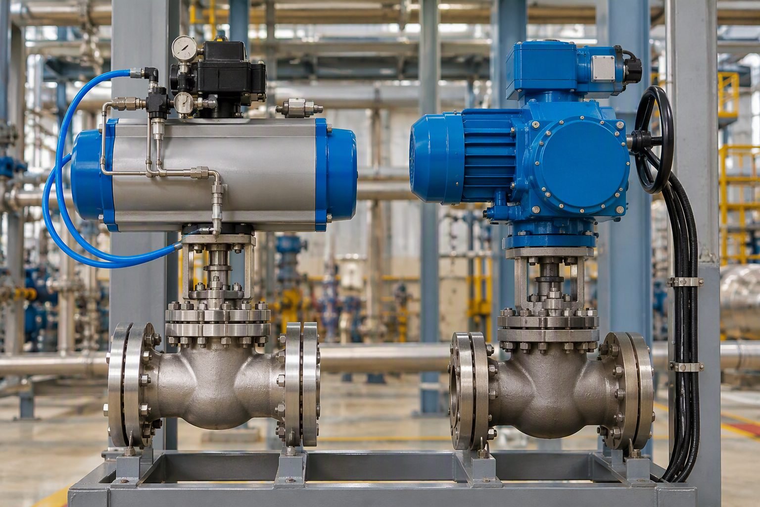
Diagnosing Control Valve Noise and Preventing Trim Failure
In my two decades of reviewing piping systems and commissioning process units, I have learned that an unusually noisy control valve is rarely just an operational nuisance. When I walk past a high-pressure drop letdown station and hear that harsh, gravelly roar, my engineering instincts immediately trigger a mental flag for severe cavitation or aerodynamic choking. Ignoring these acoustic signatures in piping infrastructure invites rapid material erosion, vibrating instrument lines to fatigue failure, and ultimately shutting down production units unexpectedly.
Modern diagnostic techniques have moved far beyond simply listening through a mechanic’s stethoscope. By combining portable acoustic sensors with vibration monitoring directly on the valve body, we can quantify the exact frequency and intensity of internal turbulence. This article details how to deploy these diagnostic methods systematically, aligning field observations with established international codes to protect your critical assets.
Key Engineering Takeaways
- Identify cavitation versus liquid flashing through high-frequency acoustic emission signatures.
- Apply IEC 60534-8-4 calculation methodologies to predict internal hydrodynamic noise levels accurately.
- Deploy handheld accelerometers to capture valve body vibration spectra linked to plug instability.
- Implement geometric trim modifications before fluid velocities induce catastrophic body wall thinning.
Acoustic Diagnostics and Control Valve Noise Mechanisms
When sizing and operating control valves, understanding the root cause of sound generation is critical for long-term mechanical integrity. Acoustic energy in valves originates from three primary sources: mechanical vibration of the trim and stem, hydrodynamic processes in liquid service, and aerodynamic turbulence in compressible gas or steam service. Each mechanism exhibits distinct frequency characteristics that allow diagnostic technicians to pinpoint internal distress without disassembling the pipeline.
In liquid applications, the most destructive noise source is cavitation. As liquid accelerates through the restricted flow area of the valve trim, local static pressure drops below the vapor pressure of the fluid, forming vapor bubbles. When the fluid recovers downstream and pressure rises above vapor pressure, these bubbles collapse violently near the solid boundary of the plug and seat. This micro-jetting generates localized pressure spikes exceeding 1000 bar, producing a characteristic high-frequency hissing sound that transitions to a roaring gravel-like noise as damage escalates.
Critical Operating Warning
Allowing a control valve to operate in advanced cavitation for more than a few hundred hours will structurally compromise standard metal trim. Always cross-reference your pressure drop ratio against the valve’s cavitation index (ISA standards) during initial plant commissioning phases.
To evaluate these phenomena systematically, engineers rely heavily on the calculation framework established in IEC 60534-8-4 for hydrodynamic noise, and IEC 60534-8-3 for aerodynamic noise. These standards provide mathematical models to predict internal sound pressure levels based on mass flow rate, pressure drop, upstream pressure, and valve recovery coefficients.
The mathematical evaluation of hydrodynamic noise begins by determining the internal acoustic power level. The acoustic power generated by the liquid jet, denoted as W, is calculated using the empirical relationship scaled against the total pressure drop across the restriction. The internal acoustic efficiency factor (eta) scales exponentially with the cavitation parameter sigma (σ), defined as:
Where P_1 is the upstream absolute pressure, Pv is the liquid vapor pressure at operating temperature, and P_2 is the downstream absolute pressure. When σ drops below the incipient cavitation limit (σ_i), bubble collapse initiates. When it falls below the critical choking cavitation limit (σ_vc), maximum damage intensity occurs.
Acoustic monitoring devices capture these high-frequency stress waves by mounting piezoelectric sensors directly onto the valve body wall or downstream piping. The sensor measures acceleration spectra in g-units across a frequency range from 1 kHz to 50 kHz. Clean single-phase liquid flow exhibits a smooth, low-amplitude baseline. As cavitation or flashing starts, high-frequency spikes emerge between 10 kHz and 30 kHz, clearly distinguishable from low-frequency mechanical vibration caused by loose packing or guide wear, which typically registers below 500 Hz.
In gas and steam services, aerodynamic noise dominates due to turbulent mixing of high-velocity jets exiting the trim orifices. When the jet velocity reaches sonic or supersonic speeds, discrete shock cells form, generating broadband acoustic energy. This manifests as an intense screeching sound that can easily exceed 100 dBA at a distance of one meter. Prolonged exposure to this energy level fatigues thin-wall piping downstream, often resulting in circumferential cracking adjacent to the outlet flange welds.
Mitigating these high-energy noise sources requires strategic hardware interventions. For liquid cavitation, replacing standard single-stage plugs with multi-stage pressure-drop trim—such as labyrinth disks or stacked plate assemblies—forces the pressure drop to occur in controlled stages. This keeps the intermediate pressures above the vapor pressure. For gas applications, low-noise multi-hole cage guided trims break the single large jet into hundreds of smaller micro-jets, shifting acoustic energy into higher, more rapidly attenuating ultrasonic frequencies.
Advantages
- ✓ Enables non-invasive detection of internal trim degradation while the process unit remains fully operational.
- ✓ Provides early warning of cavitation before mechanical erosion penetrates the outer valve body wall.
- ✓ Aligns empirical field readings directly with IEC 60534-8-4 predictive calculation models.
- ✓ Reduces unexpected emergency shutdowns by facilitating data-driven preventative maintenance scheduling.
- ✓ Distinguishes clearly between aerodynamic turbulence, hydrodynamic cavitation, and mechanical component rattling.
Disadvantages
- ✗ High-frequency acoustic signal interpretation requires specialized technical training and experienced diagnostic personnel.
- ✗ External background noise from adjacent high-pressure piping can mask subtle internal valve acoustic signatures.
- ✗ Portable sensor coupling quality heavily influences data repeatability and baseline consistency.
- ✗ Does not physically repair existing trim damage, serving purely as an analytical diagnostic indicator.
- ✗ Initial capital investment for high-end acoustic emission hardware and spectrum analyzers can be substantial.
High-Pressure Boiler Feedwater Systems
Boiler feedwater pump recirculation control valves experience extreme pressure drops and severe fluid subcooling conditions. Deploying acoustic monitoring on these high-head letdown valves identifies incipient flashing and cavitation before pitting destroys expensive stellite-faced trim components, ensuring uninterrupted steam generation.
Refinery Hydroprocessing Reactor Letdown
Hydrocracker and desulfurization high-pressure letdown valves handle aggressive multi-phase hydrocarbon streams at elevated temperatures. Acoustic emission surveys verify that multi-stage tungsten carbide trim assemblies are operating within allowable hydrodynamic turbulence limits, preventing catastrophic body wall breakthrough.Natural Gas Compressor Station Blowdown
Gas pipeline compressor stations utilize large automated blowdown valves that experience extreme acoustic fatigue during emergency venting. Vibration and high-frequency sound diagnostics evaluate the structural integrity of downstream piping elbows, ensuring compliance with strict environmental noise regulations and ASME codes.Chemical Plant Cryogenic Service Valves
Liquefied natural gas and low-temperature chemical processing plants manage extremely dense fluids where flashing is highly probable. Acoustic monitoring identifies localized boiling phenomena within cryogenic control valve bodies, preventing thermal shock and mechanical binding of sliding stem assemblies.Power Plant Steam Turbine Bypass Stations
High-pressure steam bypass systems dump superheated steam directly to condensers during turbine trips, creating immense aerodynamic noise. Acoustic and vibration screening detects high-velocity vortex shedding and trim chatter, protecting downstream attemperator piping from fatigue-induced weld failures.Control Valve Noise Evaluation Parameters
Evaluating control valve noise requires a rigorous understanding of fluid velocity, pressure drop ratios, and acoustic frequencies generated across the valve trim. When diagnosing potential trim failure, engineers rely on standardized acoustic data to separate normal hydrodynamic turbulence from destructive cavitation and aerodynamic chokeflow. The following operational matrix details the critical diagnostic thresholds established by ISA and IEC 60534-8-4 standards for industrial process control loops.
The data below outlines specific frequency signatures, decibel limits measured at one meter from the pipe wall, and corresponding mechanical failure modes. Utilizing this quantitative baseline helps reliability teams schedule targeted maintenance before severe erosion compromises valve integrity or process containment.
| Acoustic Parameter | Normal Operation | Warning Threshold | Failure Mode Indication |
|---|---|---|---|
| Overall Sound Pressure Level | < 85 dBA at 1 meter | 85 dBA to 95 dBA | High turbulence, incipient cavitation |
| Vibration Acceleration | < 0.5 g peak | 0.5 g to 1.5 g peak | Trim chattering, plug instability |
| Dominant Frequency Peak | < 500 Hz (Broadband) | 1,000 Hz to 4,000 Hz | Aerodynamic jet noise, shear layer rattle |
| Ultrasonic Acoustic Emission | < 30 dB mV | 30 dB mV to 60 dB mV | Vapor bubble collapse, micro-jet pitting |
Note: Measurements exceeding warning thresholds for more than seventy-two continuous operational hours mandate internal trim inspection per ASME guidelines.
Technical Mapping & Specifications Matrix
Modern plant asset management requires structured entity mapping to correlate physical sensor data with engineering standards. The following matrix links acoustic and vibration monitoring variables with recognized industrial codes, regulatory bodies, and specific failure mechanisms encountered in high-pressure service control valves.
System integrators and reliability engineers use this cross-reference matrix during root-cause analysis to ensure compliance with international testing protocols and to select appropriate mitigation hardware, such as multi-stage anti-cavitation trims or low-noise diffusers.
| Entity Category | Standard / Code | Core Variable | Engineering Application |
|---|---|---|---|
| Acoustic Prediction | IEC 60534-8-4 | Sound Pressure Level (SPL) | Predicting aerodynamic noise in gas and vapor valves |
| Hydrodynamic Noise | IEC 60534-8-3 | Cavitation Noise Spectrum | Evaluating liquid flow choking and bubble collapse energy |
| Valve Sizing & Design | ANSI/ISA-75.01.01 | Pressure Recovery Factor (FL) | Determining choke limits and pressure drop ratios |
| Vibration Testing | ISO 10816-1 | RMS Velocity / Acceleration | Assessing overall mechanical severity on process piping |
Proper utilization of these standards ensures that acoustic diagnostics yield actionable data for plant turnaround planning and regulatory environmental compliance.
Site Verification Checklist for Control Valve Noise
Executing a systematic field audit requires strict adherence to validation rules before placing diagnostic transducers on live process equipment. Technicians must verify acoustic sensor calibration, coupling grease integrity, and baseline operating conditions to ensure accurate identification of valve trim damage.
The structured checklist below outlines mandatory site verification checkpoints that must be completed prior to opening or overhauling any critical control valve assembly in high-pressure hydrocarbon service.
Acoustic and Vibration Site Inspection Protocol
- Sensor Coupling Verification: Ensure accelerometer magnetic base or mounting stud is firmly attached to bare metal on the valve body wall, free of heavy paint or corrosion scale.
- Operating State Logging: Record exact process pressure drop, upstream temperature, mass flow rate, and valve travel percentage during the acoustic sweep.
- Background Noise Isolation: Measure ambient acoustical levels at 1 meter to isolate adjacent pump or compressor noise from the specific valve under test.
- Frequency Spectrum Analysis: Compare captured FFT peaks against IEC 60534-8-4 calculation models to identify cavitation versus aerodynamic jet noise.
- Actuator Stability Check: Inspect pneumatic positioner linkage and stem clamping for mechanical backlash that could amplify vibration signatures.
Completing these verification steps eliminates false positives caused by loose mounting hardware or improper process operating points, ensuring high reliability for predictive maintenance programs.
Field Case Study: Real-World Application
In my experience commissioning a high-capacity hydroprocessing unit, an 8-inch letdown control valve began emitting a piercing acoustic whine and severe pipe vibration when operating at 40 percent stem opening. Initial plant operations dismissed the sound as standard high-pressure drop turbulence, but maintenance reliability teams intervened with handheld acoustic and vibration diagnostic tools to prevent an uncalculated shutdown.
Problem Analysis:
Severe trim degradation occurred due to unchecked hydrodynamic cavitation and high-frequency plug oscillation.
- Sound pressure level readings reached 102 dBA at 1 meter, far exceeding plant safety limits.
- High-frequency ultrasonic peaks between 3,000 Hz and 5,000 Hz confirmed active bubble collapse against the plug.
- Process pressure drop across the single-stage trim exceeded 3.5 MPa, violating safe operating envelopes.
- Inspection during a brief outage revealed deep pitting on the tungsten carbide plug seating surface.
To resolve the failure, engineering implemented a comprehensive redesign of the valve internals in accordance with IEC 60534-8-4 guidelines, replacing the standard plug with a multi-stage pressure management trim.
Case Outcome:
Successful elimination of destructive cavitation noise and restoration of stable control loop performance.
- Overall sound pressure level dropped from 102 dBA down to a safe 78 dBA during peak flow.
- Vibration acceleration reduced from 2.1 g peak to 0.3 g peak, protecting adjacent piping welds.
- Multi-stage trim successfully staged the pressure drop, preventing further metal loss on the plug.
- Plant avoided an unplanned emergency outage valued at over 1.2 million dollars in lost production.
Recommendation: Establish routine acoustic monitoring frequencies on all high-delta-P letdown valves during initial startup phases to catch trim damage before catastrophic structural failure occurs.
Frequently Asked Engineering Questions
What causes excessive hydrodynamic noise in control valves?
- High pressure drop ratios that exceed the valve manufacturer critical cavitation index threshold.
- Improper plug and seat selection that creates sharp flow separation zones.
- Unfavorable downstream piping geometry causing abrupt velocity spikes.
How does IEC 60534-8-4 predict aerodynamic valve noise?
- Upstream absolute pressure and total mass flow rate driving turbulent kinetic energy.
- Internal trim recovery characteristics and jet velocity profile expansion.
- Pipe wall coincidence frequency and acoustic transmission loss coefficients.
What are the primary indicators of valve trim damage?
- A sudden broadband high-frequency hiss shifting into a low-frequency gravel-like rumble.
- High-amplitude acceleration spikes detected via surface-mounted piezoelectric accelerometers.
- Degraded loop control performance characterized by increased valve stiction and deadband.
How do acoustic sensors locate internal leakage paths?
- Decibel amplitude peaks centered in the 30 kHz to 100 kHz frequency spectrum.
- Signal attenuation gradients measured across upstream and downstream pipe spool lengths.
- Correlation between actuator seating force and measured high-frequency RMS levels.
What mitigation trims reduce aerodynamic noise effectively?
- Multi-stage labyrinth disk stacks that force fluid through numerous right-angle turns.
- Drilled-hole cage designs that break large continuous jets into tiny individual streams.
- Downstream inline silencers and expansion diffusers for high-flow gas transmission lines.
Field Recommendation
Based on my two decades of hands-on commissioning and troubleshooting across major process facilities, mitigating control valve noise requires a proactive, multidisciplinary engineering approach rather than reactive component replacement. When addressing stubborn acoustic issues or suspected trim degradation on critical high-energy loops, I advise my site teams to apply the following actionable field rules:
- If continuous baseline acoustic monitoring indicates decibel levels exceeding 85 dBA at one meter, immediately schedule a diagnostic vibration survey prior to the next scheduled turnaround to prevent unguided stem fatigue failure.
- If standard single-stage valve trims experience recurrent cavitation damage within six months of commissioning, upgrade the assembly to a multi-stage stepped pressure drop cage designed in strict accordance with ISO standards.
- If high-pressure gas letdown valves generate severe aerodynamic whistling, install an inline porous plate silencer downstream combined with a high-mass heavy-wall piping spool to damp shell vibration modes effectively.
- If ultrasonic acoustic emission testing reveals seat bypass leakage during plant startup, verify actuator bench set calibration and seating thrust force before dispatching the valve trim for expensive machine shop refurbishment.
- If complex multi-phase fluid conditions obscure traditional acoustic signatures, deploy combined accelerometer and high-frequency microphone arrays to isolate mechanical impact frequencies from fluid-borne turbulence.
Adopting these rigorous diagnostic and hardware selection practices will protect your plant infrastructure, eliminate unscheduled downtime, and ensure long-term mechanical integrity across all critical control loops.
Complete Course on
Piping Engineering
Check Now
Key Features
- 125+ Hours Content
- 500+ Recorded Lectures
- 20+ Years Exp.
- Lifetime Access
Coverage
- Codes & Standards
- Layouts & Design
- Material Eng.
- Stress Analysis
