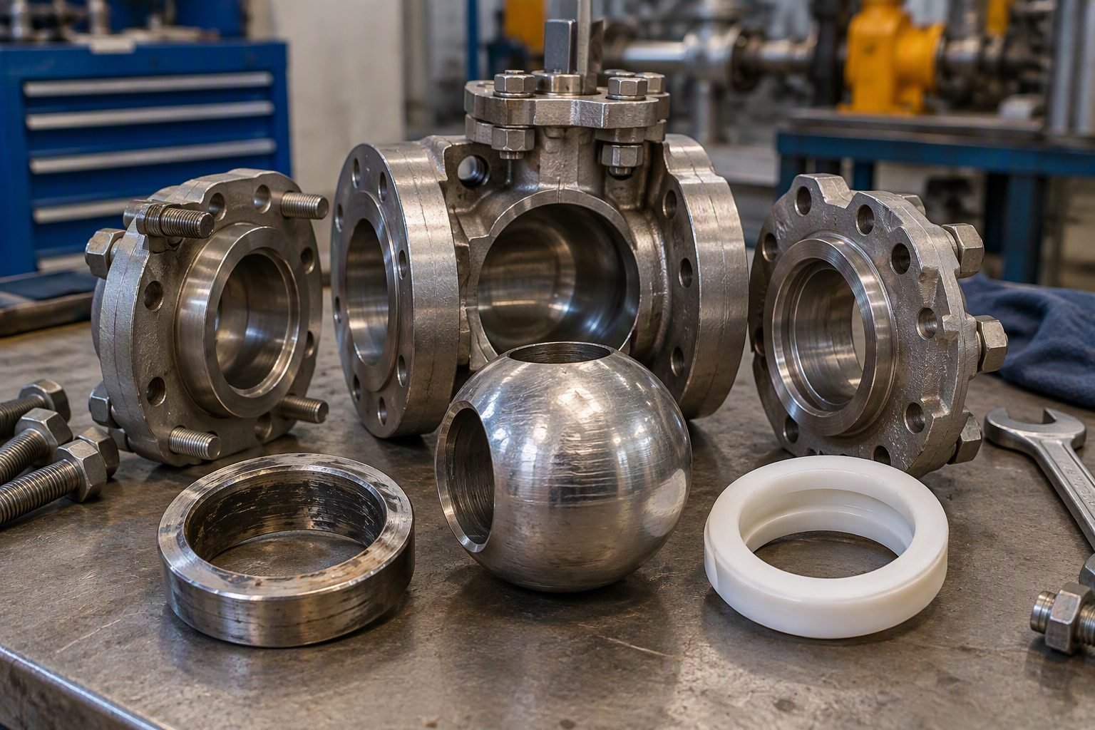
How to Prevent Control Valve Cavitation in Piping Systems
In my 20-plus years of piping engineering, I have seen control valves literally eaten away from the inside out within weeks of commissioning. The culprit is almost always a failure to anticipate the destructive forces of localized phase changes. When high-velocity liquid passes through the vena contracta, the pressure drops below the vapor pressure, forming tiny vapor bubbles. As the pressure recovers downstream, these bubbles collapse violently, generating micro-jets with localized pressures up to 100,000 psi that destroy metal surfaces.
To protect your piping infrastructure, you must design out these localized pressure drops. This guide walks you through the exact sizing methods, physics, and trim technologies required to eliminate cavitation damage.
- Understand the physical mechanics of cavitation and how to identify early-stage trim erosion.
- Apply ISA-75.01.01 sizing equations to calculate the cavitation index and predict damage.
- Evaluate multi-stage cage designs and alternative materials to protect your piping infrastructure.
Mitigating Control Valve Cavitation in High-Pressure Systems
To understand cavitation, we must look at the pressure profile of a fluid as it travels through a control valve. As the fluid approaches the valve restriction (the trim), the flow area decreases. To maintain a constant volumetric flow rate, the fluid velocity must increase. This velocity spike causes a corresponding drop in static pressure, reaching its lowest point at the vena contracta, which is the narrowest point of the fluid stream.
If the static pressure at the vena contracta falls below the vapor pressure of the liquid at the operating temperature, the liquid flashes into vapor. This phase change creates millions of tiny vapor bubbles. As the fluid moves past the vena contracta into the wider downstream piping, the velocity decreases and the static pressure recovers.
When this recovered pressure rises back above the vapor pressure, the vapor bubbles become unstable and collapse. The surrounding liquid rushes in to fill the void left by the collapsing bubble, creating a micro-jet of liquid. These micro-jets strike the internal metal surfaces of the valve trim and body at supersonic speeds. The resulting mechanical impact causes localized fatigue, leading to a distinctive pitted, “cinder-like” appearance on the metal.
The Liquid Pressure Recovery Factor
The susceptibility of a valve to cavitation is heavily influenced by its internal geometry, which is quantified by the Liquid Pressure Recovery Factor, denoted as FL. This factor is a dimensionless ratio that describes the valve’s ability to convert kinetic energy back into static pressure.
High-recovery valves, such as ball and butterfly valves, have low FL values, typically ranging from 0.5 to 0.7. These valves allow the pressure to drop deeply at the vena contracta, followed by a high pressure recovery downstream. This profile makes them highly susceptible to cavitation.
Low-recovery valves, such as globe valves, have high FL values, often between 0.85 and 0.9. These valves dissipate energy through turbulence and friction, resulting in a much higher vena contracta pressure for the same overall pressure drop. This characteristic makes globe valves the preferred choice for severe service applications where cavitation is a risk.
Sizing Methods to Prevent Control Valve Cavitation
The standard sizing methodology defined by ISA-75.01.01 uses the liquid critical pressure ratio factor, FF, to predict choked flow and cavitation. The equation for FF is:
FF = 0.96 – 0.28 * sqrt(Pv / Pc)
Where Pv is the vapor pressure of the liquid at inlet temperature, and Pc is the thermodynamic critical pressure of the liquid. Once FF is established, we calculate the maximum allowable pressure drop, Delta P-max, that the valve can handle before choked flow occurs:
Delta P-max = FL^2 * (P1 – FF * Pv)
Where P1 is the upstream inlet pressure. If the actual service pressure drop (P1 – P2) is greater than Delta P-max, the valve will operate in a choked condition, and severe cavitation is highly likely.
To evaluate the severity of cavitation before it reaches a fully choked state, we use the cavitation index, sigma:
sigma = (P1 – Pv) / (P1 – P2)
A high sigma value indicates a low risk of cavitation. As the downstream pressure P2 decreases, the pressure drop increases, and the sigma value drops. When sigma falls below the manufacturer’s recommended threshold for a specific valve geometry, specialized trim must be selected.
Multi-stage trim designs solve this issue by splitting the total pressure drop into several smaller, controlled steps. By dividing the pressure drop across three, four, or more stages, the static pressure at each individual stage is kept safely above the vapor pressure of the fluid. This design prevents the fluid from ever reaching its boiling point, completely eliminating bubble formation.
- Eliminates cavitation damage by preventing bubble collapse near metal boundaries.
- Reduces aerodynamic and hydrodynamic noise levels by up to 30 decibels.
- Minimizes mechanical vibration, protecting downstream piping welds and instruments.
- Extends the mean time between failures (MTBF) of severe service control valves.
- Improves process control stability by preventing choked flow conditions.
- Significantly higher initial capital cost compared to standard single-stage trim.
- High susceptibility to plugging and clogging if the process fluid contains suspended solids.
- Increased physical size and weight, requiring robust piping supports and actuators.
- Complex maintenance procedures requiring specialized training and alignment tools.
- Reduced maximum flow capacity (Cv) for a given valve body size due to restricted flow paths.
Cavitation Index Limits: These design parameters establish the operational boundaries for control valves under high pressure drop conditions to prevent severe trim erosion. By calculating the cavitation index according to ISA-75.01.01, piping engineers can select appropriate trim geometries and hardened materials.
In my 20 years of piping engineering, I have seen countless control valves destroyed by ignoring the relationship between the cavitation index and material hardness. The table below outlines the thresholds where standard single-stage trims fail and multi-stage cages or hardened alloys become mandatory. These limits are derived from field performance data and standard industry practices. Selecting the wrong combination leads to rapid valve trim erosion and catastrophic pressure boundary failure.
| Cavitation Index (Sigma) | Damage Risk | Recommended Trim Design | Recommended Material |
|---|---|---|---|
| Sigma > 2.0 | Negligible | Standard Linear or Equal Percentage | Carbon Steel or 316 Stainless Steel |
| 1.5 < Sigma <= 2.0 | Light | Single-stage Perforated Cage | 316 Stainless Steel with Stellite Facing |
| 1.0 < Sigma <= 1.5 | Moderate to Severe | Multi-stage Perforated Trim | Hardened 440C Stainless Steel or Tungsten Carbide |
| Sigma <= 1.0 | Choked or Extreme | Multi-stage Cascade or Path Trim | Solid Tungsten Carbide or Ceramic |
Operating a valve continuously within the moderate to severe range without hardened trim guarantees premature failure. I always recommend specifying a multi-stage cage when the calculated pressure drop ratio exceeds the terminal pressure drop ratio of the valve. This table serves as a primary screening tool during the initial process design phase. It ensures that your piping system remains intact and free from severe vibration.
In my experience, ignoring these material guidelines leads to localized pitting that can breach the valve body within weeks of commissioning. Hardened materials like Stellite 6 or tungsten carbide provide the necessary resistance against the high-velocity micro-jets formed during bubble collapse. You must verify these selections during the detailed engineering phase.
Technical Specifications Matrix: This engineering reference maps the core physical parameters, standards, and design variables required to mitigate control valve cavitation. It aligns the mathematical criteria of ISA-75.01.01 with physical trim characteristics to ensure long-term mechanical integrity.
To design a system that resists cavitation, you must understand how different physical parameters interact. This matrix maps key technical entities, their governing standards, and their direct impact on control valve cavitation. I use this mapping during design reviews to verify that all process variables have been accounted for. It helps bridge the gap between process conditions and mechanical valve design.
| Entity Name | Governing Standard | Physical Parameter | Design Impact |
|---|---|---|---|
| Liquid Pressure Recovery Factor (FL) | ISA-75.01.01 | Dimensionless ratio of pressure recovery | Determines the onset of choked flow and cavitation. |
| Vapor Pressure (Pv) | ASTM D323 | Absolute pressure at operating temperature | Defines the threshold where vapor bubbles form in the vena contracta. |
| Multi-stage Cage | ASME B16.34 | Number of pressure reduction stages | Splits the total pressure drop across multiple steps to keep local pressure above vapor pressure. |
| Valve Trim Erosion | NACE MR0175 | Material loss rate in millimeters per year | Dictates the maintenance interval and material selection for the valve internals. |
Each entity in this matrix plays a specific role in the overall sizing equation. For instance, the liquid pressure recovery factor is highly dependent on the internal geometry of the valve. A high-recovery valve like a ball valve is far more susceptible to cavitation than a low-recovery globe valve. By analyzing these parameters early, you can avoid costly field modifications and piping vibration issues.
In my experience, process engineers often overlook the vapor pressure variation at elevated temperatures. A small temperature spike can drastically increase the vapor pressure, pushing a stable valve into a severe cavitating regime. Always design for the maximum operating temperature rather than just the normal operating point.
Site Verification Checklist: This field inspection protocol outlines the mandatory physical checks and data verification steps required to diagnose and prevent control valve cavitation. It ensures compliance with ISA-75.01.01 sizing assumptions during field commissioning.
Before you sign off on a newly installed control valve or troubleshoot an existing one, a structured field inspection is mandatory. I have developed this checklist over two decades of resolving severe valve trim erosion issues in high-pressure water systems. It covers physical inspection, process data verification, and acoustic monitoring.
- Verify that the valve flow direction matches the arrow cast on the body (flow-to-open vs. flow-to-close).
- Measure upstream and downstream piping pressures to calculate the actual operating cavitation index.
- Check for the characteristic “gravel-like” noise using an acoustic transmitter or stethoscope.
- Inspect the downstream piping for localized vibration and verify that pipe supports are secure.
- Confirm that the multi-stage cage is free from debris that could block the small flow passages.
- Verify that the valve travel matches the controller output to ensure the trim operates in its designed range.
If you detect a noise level exceeding 85 dBA near the valve, it is highly likely that cavitation is occurring. You must immediately cross-reference the actual pressure drop with the valve’s liquid pressure recovery factor. In my experience, many field issues stem from installing the valve backward. For cavitating service, a flow-over-the-plug configuration is sometimes used to keep the bubbles in the center of the flow stream, protecting the body walls.
Ensure that the upstream straight pipe run is at least 10 pipe diameters and the downstream run is at least 5 pipe diameters to maintain stable flow profiles. This prevents turbulent flow from exacerbating localized pressure drops. When inspecting the physical trim during a turnaround, look for a dull, pitted appearance resembling Swiss cheese. This is a classic sign of valve trim erosion caused by micro-jets.
If you find this damage, you must upgrade to a multi-stage cage or a harder material like tungsten carbide. Regular monitoring of downstream pipe wall thickness using ultrasonic testing is also highly recommended to prevent catastrophic line ruptures.
Field Case Study: Real-World Application
Field Case Study: This technical analysis documents the diagnostic steps and engineering solutions applied to resolve severe control valve cavitation in a high-pressure boiler feed system. It demonstrates the practical application of ISA-75.01.01 standards to eliminate valve trim erosion.
I was called to a combined-cycle power plant where the main boiler feedwater control valve was failing every three months. The plant was experiencing severe piping vibration and a deafening noise that made the area unsafe for operators. The valve was a standard single-stage globe valve operating under a pressure drop of 120 bar. The high-velocity fluid was flashing in the vena contracta, and the subsequent pressure recovery was collapsing vapor bubbles directly against the plug and seat.
The existing single-stage control valve suffered from extreme cavitation damage due to a high pressure drop that exceeded the valve’s recovery limits. The localized micro-jets generated during bubble collapse were eroding the metal at an alarming rate.
- Operating pressure drop of 120 bar, which was far above the vapor pressure threshold of the 150 degree Celsius feedwater.
- Use of a standard single-stage linear trim with a low liquid pressure recovery factor of 0.75.
- Standard 316 stainless steel trim material without any hardening or Stellite facing, leading to rapid pitting.
- Inadequate downstream straight pipe run, which amplified the acoustic energy and vibration.
- Lack of upstream pressure stabilization, causing erratic valve positioning and unstable control loops.
Replacing the valve with a custom-engineered multi-stage cage trim completely eliminated the cavitation damage and restored system stability. The new design utilized a six-stage concentric cage to drop the pressure gradually, keeping the local pressure above the fluid’s vapor pressure at every stage.
- Noise levels dropped from an unsafe 98 dBA to a compliant 78 dBA at 1 meter, meeting OSHA standards.
- The valve service life extended from 3 months to over 4 years without requiring trim replacement.
- Piping vibration was reduced by 85%, protecting downstream instrumentation and supports.
- The plant avoided unscheduled shutdowns, saving an estimated 150,000 in annual maintenance costs.
- The control loop stability improved, reducing process variability in the steam drum level control.
Based on this experience, I recommend that any control valve operating with a pressure drop exceeding 30 bar in liquid service undergo a formal cavitation analysis. Do not rely on standard trims for high-energy applications. Specifying a multi-stage cage during the design phase is always more cost-effective than retrofitting a failing valve in an operating plant. You must also ensure that the valve body material is selected to resist erosion-corrosion, especially in high-temperature feedwater systems.
Frequently Asked Engineering Questions
How does ISA-75.01.01 help predict control valve cavitation?
- It defines the pressure differential ratio limit where cavitation begins.
- It calculates the choked flow rate to prevent sizing errors.
- It establishes the cavitation index to assess damage risk.
What is the difference between cavitation and flashing in globe valves?
- Cavitation occurs when downstream pressure recovers above vapor pressure, collapsing bubbles.
- Flashing occurs when downstream pressure remains below vapor pressure, keeping the fluid in a two-phase state.
- Cavitation causes severe localized pitting, while flashing causes smooth, polished erosion.
Why are multi-stage perforated cages effective against cavitation damage?
- They keep the local pressure in each stage above the fluid’s vapor pressure.
- They direct collapsing bubbles toward the center of the flow stream, away from metal walls.
- They reduce fluid velocity, which exponentially lowers the rate of trim erosion.
When should I upgrade from a single-stage to a multi-stage trim?
- When the pressure drop ratio exceeds 0.5.
- When calculated noise levels exceed 85 dBA during continuous operation.
- When inspection reveals severe pitting on the plug or cage within six months of commissioning.
Can downstream piping geometry influence control valve cavitation?
- Abrupt expansions or elbows close to the valve outlet alter the pressure recovery factor.
- Insufficient straight run downstream can intensify localized turbulence and bubble collapse.
- Installing a downstream concentric expander helps maintain stable backpressure.
What materials offer the best resistance to valve trim erosion?
- Stellite 6 overlays provide excellent resistance to thermal shock and mechanical pitting.
- Solid tungsten carbide is preferred for severe service applications with high pressure drops.
- Hardened stainless steels like 410 or 17-4 PH offer cost-effective protection in moderate conditions.
- If your process fluid exhibits a cavitation index (sigma) below 1.5, I recommend bypassing standard single-stage trims entirely and specifying a multi-stage perforated cage to prevent rapid mechanical failure.
- In my experience, when retrofitting existing globe valves suffering from severe trim erosion, you should verify downstream piping straight runs of at least 10 nominal diameters before upgrading the trim material to solid tungsten carbide.
- If the calculated pressure drop across the valve exceeds 50 bar, choose a multi-stage trim with at least three pressure-reduction stages to ensure the local pressure never drops below the fluid’s vapor pressure.
- When budget constraints limit trim upgrades, I advise installing a downstream restriction orifice plate as a sacrificial backpressure device, provided the flow rate remains relatively constant.
Complete Course on
Piping Engineering
Check Now
Key Features
- 125+ Hours Content
- 500+ Recorded Lectures
- 20+ Years Exp.
- Lifetime Access
Coverage
- Codes & Standards
- Layouts & Design
- Material Eng.
- Stress Analysis
