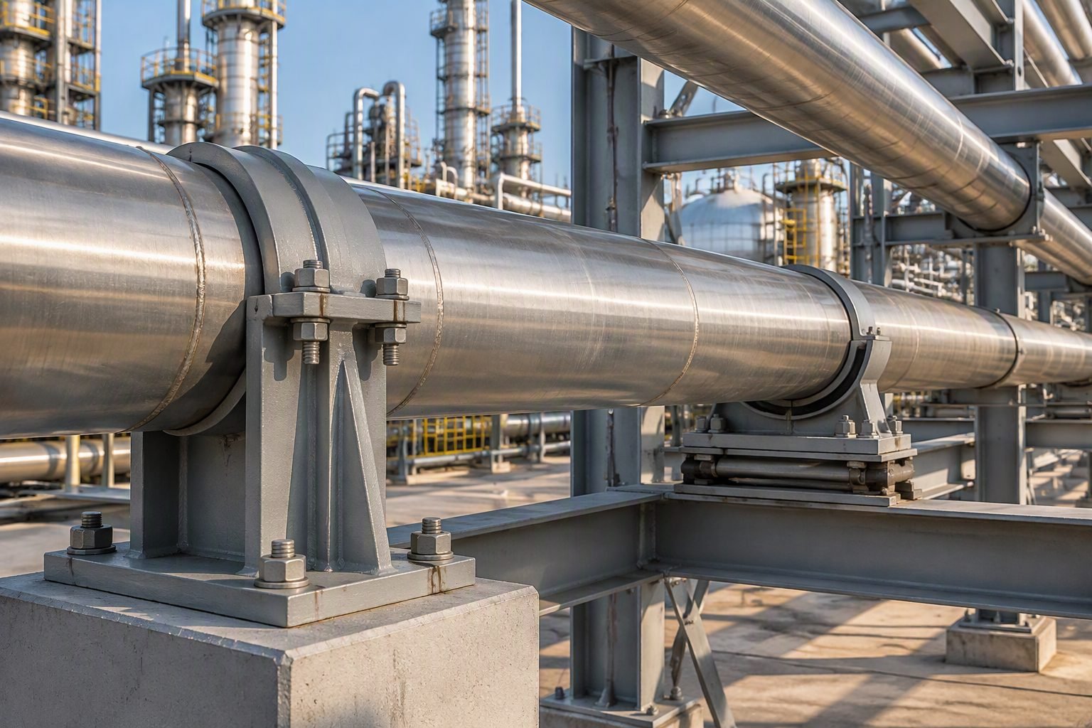
Engineering a Fixed Anchor Bracket Clamp for Cladded Piping Systems
In my two decades of reviewing complex thermal stress models for high-temperature hydrocarbon units, managing thermal growth at directional changes remains one of the most critical mechanical challenges. When high-temperature process piping experiences severe thermal expansion, unmitigated growth can overstress equipment nozzles and destroy delicate internal cladding. To protect the pressure boundary while preserving alloy linings, piping engineers rely on a robust fixed anchor bracket clamp rigidly bolted to a reinforced concrete pedestal.
Designing this assembly requires meticulous attention to friction forces, local shell stresses on the carrier pipe, and the shear transfer capacity of anchor bolts embedded in concrete. In this engineering guide, I will walk you through the rigorous mechanical design, stress interaction limits, and structural detailing required to restrain all six degrees of freedom safely per international piping codes.
Key Engineering Takeaways
- Restraining all six degrees of freedom requires zero axial, lateral, and rotational displacement at the anchor point.
- Cladded piping demands careful clamp sizing to avoid crushing the outer protective jacket or damaging the internal alloy liner.
- Anchor brackets must transfer high frictional and axial thrust loads directly into concrete pedestals per ASME BPVC Section VIII and ACI 349 guidelines.
- Rigid thermal anchoring forces axial growth to split symmetrically toward adjacent expansion loops or bellows.
ASME B31.3 Design Criteria for Fixed Anchor Bracket Clamps
When designing a fixed anchor bracket clamp for cladded process piping, my primary objective is to lock all six degrees of freedom—three translational axes (X, Y, Z) and three rotational axes (Rx, Ry, Rz)—without inducing localized wall thinning or stress concentrations. In high-temperature service exceeding 400 degrees Celsius, thermal growth generates immense axial thrust forces. These forces must be absorbed entirely by the anchor structure rather than being transmitted to sensitive equipment nozzles.
The structural load path begins at the cladded pipe wall, transfers through the alloy or carbon steel clamp halves, travels down through shear lugs and gusseted base plates, and terminates at the reinforced concrete pedestal via heavy-duty cast-in-place anchor bolts. Per ASME B31.3, piping supports and anchors must be designed to withstand the sum of sustained loads, thermal expansion loads, and occasional loads such as wind and seismic events.
Calculations for Thermal Thrust and Friction Forces
To size the clamp bolts and structural gussets, I calculate the maximum thermal thrust force (F_thermal) generated by the restrained pipe segment. The formula accounts for the modulus of elasticity (E), cross-sectional area of the pipe metal (A), coefficient of thermal expansion (α), and temperature differential (Δ T):
In addition to pure axial thrust, friction forces between the clamp inner surface and the pipe cladding must be evaluated. For stainless steel cladding clamped with high-alloy bolts, assuming a static friction coefficient (μ) of 0.3, the clamping preload must generate sufficient normal force to prevent micro-slippage under cyclic thermal variations, which would otherwise lead to fretting corrosion.
Engineering Warning: Clad Crushing and Local Stresses
Cladded piping features a thin corrosion-resistant alloy layer bonded to a heavier carbon or low-alloy steel backing. Excessive bolt torque on the anchor clamp can crush the softer cladding layer or induce high radial pinch stresses (local hoop bending) in the carrier pipe wall.
Always verify local stresses using Welding Research Council Bulletin 107 or 537 (WRC 107/537) analytical methods to ensure radial loads from the bracket do not exceed allowable local shell stress limits.
Restraining All Six Degrees of Freedom
Achieving a true six-degree-of-freedom restraint requires specific structural detailing. Translating X, Y, and Z movements to zero is accomplished by combining heavy clamping friction with welded shear lugs or integral anchor collars. Rotational restraint (Rx, Ry, Rz) is achieved by utilizing twin clamp assemblies spaced apart or incorporating rigid moment-resisting gussets tied directly to the base plate.
When evaluating the concrete pedestal supporting this anchor, engineers must cross-reference ACI 318 and ASME BPVC Section III, Subsection NF. Concrete breakout capacity in tension and pry-out capacity in shear often govern the anchor bolt embedment depth, frequently requiring deep, heavily reinforced concrete pedestals with hairpins and confinement stirrups.
Advantages
- Provides absolute 6-DOF restraint, perfectly splitting thermal growth toward designated expansion loops.
- Eliminates reliance on friction alone when equipped with welded shear lugs, preventing pipe slippage under severe seismic shock.
- Protects delicate equipment nozzles (turbines, pumps, compressors) from excessive thermal nozzle loading.
- Allows precise pre-setting and alignment during cold-spring installation phases in high-temperature refinery units.
- Bolt-on clamp designs accommodate cladded piping without requiring full penetration field-welds directly to the alloy pressure boundary.
Disadvantages
- Induces very high localized secondary thermal stresses in the pipe wall near the clamp attachment zone.
- Requires massive reinforced concrete pedestals and deep anchor bolt embedments to resist overturning moments.
- Higher material and fabrication costs due to precision machining of heavy-gauge clamp halves and alloy shims.
- Complex thermal insulation integration, often creating thermal bridging and heat loss points at the pedestal interface.
- Demands rigorous periodic bolt retorquing and inspection to counteract high-temperature creep relaxation effects.
Refinery Catalytic Cracker Transfer Lines
Fluid Catalytic Cracking (FCC) units operate at temperatures exceeding 700 degrees Celsius with catalyst-resistant cladded piping. Fixed anchor bracket clamps are installed at major directional risers to anchor the heavy conduit, forcing thermal growth upward into suspended hangers and preventing catastrophic misalignment at regenerator vessel inlets.
Petrochemical Steam Cracker Furnace Headers
High-temperature steam cracking coils and transfer headers utilize alloy-cladded piping to resist carburization and oxidation. Rigid anchor clamps positioned at fixed mid-points between radiant coils ensure that thermal expansion is evenly split toward the quench boilers, protecting header stub welds from fatigue failure.
Synthetic Fuel Gasification Piping Systems
Coal and biomass gasification plants transport corrosive syngas at extreme pressures and temperatures through internally cladded pressure piping. Heavy fixed anchor bracket clamps secure direction-change elbows to massive concrete foundations, withstanding severe pressure thrust and transient fluid hammer forces.
Nuclear Power Plant Main Steam Lines
Secondary side high-pressure steam piping in nuclear facilities requires rigorous seismic and thermal restraint. Fixed anchor brackets rigidly clamp cladded or heavy-wall alloy lines to massive containment internal structures, restraining all six degrees of freedom to satisfy stringent nuclear safety codes.
Mechanical and Material Properties for Fixed Anchor Bracket Clamps
When designing a fixed anchor bracket clamp for high-temperature cladded piping systems, engineers must meticulously evaluate mechanical properties, thermal expansion coefficients, and load transfer limits. The table below outlines the structural properties, bolt torque requirements, and material specifications conforming to ASME B31.3 Process Piping requirements and standard ASTM material grades.
The parameters detailed in this matrix reflect standard operating conditions where radial thermal growth must be fully restricted at directional change points. Proper bolt tensioning and clamp sizing prevent localized crushing of the outer cladding while ensuring zero slippage under extreme axial and lateral reaction loads transmitted from the pipe wall.
| Parameter | Design Specification | Governing Code / Standard |
|---|---|---|
| Clamp Body Material | ASTM A516 Gr. 70 / A240 TP316H | ASTM International |
| Cladding Protection Layer | 3mm PTFE / Ceramic Insulating Saddle | MSS SP-58 / MSS Standards |
| Anchor Bolt Grade | ASTM A193 B7 / A194 Gr. 2H Heavy Hex | ASME B18.2.1 / B18.2.2 |
| Degree of Freedom Restraint | All 6 DOFs (3 Translational, 3 Rotational) | ASME B31.3 |
| Max Operating Temperature | 550 Degree Celsius (1022 Degree Fahrenheit) | ASME Section II Part D |
*Note: Bolt preload values must be verified using calibrated torque wrenches to maintain structural integrity across thermal cycles without inducing excessive radial stress on alloy cladded pipe walls.
Technical Mapping & Specifications Matrix
To ensure absolute compliance with international engineering frameworks, complex industrial installations require structured entity mapping. The following matrix correlates critical technical entities, physical parameters, and structural acronyms associated with rigid anchor bracket design and concrete pedestal interface management.
Each mapped entity links directly to its governing industrial specification, ensuring that stress engineers, civil foundation designers, and site installation teams operate under a unified technical reference architecture.
| Entity / Component | Technical Description | Primary Reference Standard |
|---|---|---|
| Concrete Pedestal | Reinforced concrete structure carrying axial and lateral anchor reaction forces to subsoil. | ACI 318 Building Code |
| Shear Lug Assembly | Welded attachment transferring longitudinal frictional and shear loads directly into the base plate. | AWS D1.1 Structural Welding |
| Anchor Bolt Embedment | Cast-in-place headed anchor bolts designed for concrete breakout and pullout resistance. | AISC Steel Construction Manual |
| Cladded Pipe Interface | Corrosion-resistant outer barrier requiring protection from local mechanical clamping indentation. | ASME B31.3 Chapter II |
*Note: Comprehensive finite element verification is recommended when reaction loads exceed 100 kilonewtons to validate local stress distribution across embedded anchor plates and concrete interfaces.
Site Verification Checklist for Fixed Anchor Brackets
Rigorous site quality control is vital prior to commissioning high-temperature piping installations. Use the structured verification protocol below to inspect pedestal preparation, clamp alignment, bolt torque uniformity, and cladding preservation in strict accordance with ASME B31.3 quality guidelines.
Installation Inspection Checkpoints
-
Pedestal Surface Planar Alignment:
Verify that the concrete pedestal top surface is level within 1 millimeter across the baseplate footprint, utilizing non-shrink epoxy grout conforming to ASTM C1107.
-
Cladding Protection Barrier Integrity:
Inspect the PTFE or elastomer insulating saddle between the clamp jaws and the cladded pipe to confirm zero metal-to-metal contact.
-
Anchor Bolt Torque Calibration:
Ensure all high-strength stud bolts are torqued in a crisscross pattern using calibrated instruments to achieve specified preload without thread galling.
-
Directional Restraint Verification:
Confirm that all six degrees of freedom are fully locked, checking for any rotational play or axial slippage under cold pull verification tests.
-
Thermal Growth Clearance Check:
Verify that adjacent guide supports and shoes maintain correct cold settings and sliding clearances prior to plant startup.
All completed checklist items must be signed off by the quality control inspector and archived in the permanent plant construction dossier for future operational audits.
Field Case Study: High-Temperature Cladded Piping Anchor Failure Analysis
During thermal commissioning of a high-pressure refinery hydroprocessing unit operating at 480 Degree Celsius, a critical direction-change fixed anchor assembly experienced severe vibration, acoustic emission, and localized deformation of the outer cladding layer.
Problem Analysis
Investigation revealed that improper clamp sizing and inadequate bolt preloading allowed micro-slippage of the cladded pipe under cyclical thermal expansion loads.
- Absence of high-temperature insulating saddles caused direct thermal bridging between the alloy pipe and carbon steel clamp.
- Uneven torque application across ASTM A193 B7 stud bolts resulted in localized crushing of the outer cladding barrier.
- Dynamic expansion forces exceeded the frictional holding threshold, transferring destructive shock waves into the concrete pedestal.
- Failure to adhere strictly to ASME B31.3 restraint design criteria led to premature support degradation.
Remediation and Outcome
The anchor assembly was completely redesigned and retrofitted with precision-engineered split-ring bracket clamps featuring high-density ceramic insulating inserts and verified bolt torques.
- All six degrees of freedom were successfully restrained without damaging the delicate outer corrosion-resistant cladding.
- Vibration levels dropped to near zero during subsequent hot operational test runs.
- Concrete pedestal stress concentrations were eliminated, restoring full structural compliance with ASME code standards.
- Long-term plant reliability was secured, preventing unplanned downtime and costly process shutdowns.
Engineering Recommendation: Always incorporate high-temperature insulating saddles and perform finite element contact stress analysis on cladded piping assemblies prior to field fabrication and installation.
Frequently Asked Engineering Questions
How does a fixed anchor bracket clamp prevent galvanic corrosion on cladded process piping?
I always isolate the carbon steel clamp from the corrosion-resistant alloy (CRA) cladding to prevent galvanic action.
- Install a compatible alloy spacer or non-metallic isolation pad (such as high-temperature mica or glass-reinforced epoxy) between the clamp and the pipe.
- Ensure the clamp bolting torque is calibrated to prevent crushing the cladding layer.
- Specify seal welding of the clamp’s integral shear lugs using matching CRA filler metal.
Why must we restrain all six degrees of freedom at a direction-change point?
Restraining all six degrees of freedom at a direction-change point is necessary to isolate thermal expansion forces and protect sensitive downstream equipment.
- It prevents the translation of high thermal expansion loads into rotating equipment nozzles per ASME B31.3.
- It stops torsional moments from twisting the piping run and causing localized overstress.
- It establishes a true structural zero-point for accurate pipe stress analysis modeling.
How do you calculate the minimum embedment depth for the pedestal anchor bolts?
Determining the embedment depth requires analyzing the combined tension and shear forces acting on the concrete pedestal.
- Apply the design methodologies outlined in ACI 318 Chapter 17 for anchoring to concrete.
- Account for concrete breakout strength, pullout strength, and pryout strength under maximum thermal load.
- Maintain a minimum embedment of 12 times the bolt diameter for high-vibration or high-temperature services.
Can we weld a fixed anchor bracket clamp directly to cladded piping?
Direct welding of structural carbon steel clamps to CRA cladding is highly discouraged due to metallurgical risks.
- Welding dissimilar metals causes carbon migration, leading to localized embrittlement and cracking.
- Any direct attachment must use a matching CRA pad welded to the pipe first, with the clamp then secured to the pad.
- Preheating and post-weld heat treatment (PWHT) must be carefully evaluated to avoid damaging the cladding bond.
What is the role of shear lugs in a fixed anchor bracket clamp assembly?
Shear lugs are key components that physically transfer axial piping loads directly into the anchor clamp assembly.
- They prevent the pipe from slipping through the clamp under high thermal thrust forces.
- They must be sized to withstand the full axial force calculated in the pipe stress analysis.
- They must be welded using qualified procedures that do not compromise the integrity of the internal cladding.
How does high-temperature service affect the selection of clamp bolting materials?
High-temperature operations cause thermal relaxation and loss of bolt tension, which can compromise the anchor’s rigidity.
- Select high-strength alloy bolting such as ASTM A193 Grade B7 or B16 to resist creep.
- Incorporate Belleville disc springs to maintain constant live-loading on the clamp halves.
- Perform regular hot-torqueing procedures during the initial plant start-up and thermal cycling phases.
- If your process operating temperature exceeds 350°C (662°F), I strongly recommend specifying ASTM A193 Grade B16 bolting with Belleville spring washers rather than standard B7 bolts. This prevents thermal relaxation and maintains the clamping force required to restrain all six degrees of freedom over extended thermal cycles.
- When anchoring cladded piping, never allow direct contact between carbon steel clamp components and the corrosion-resistant alloy cladding. In my experience, installing a 3mm thick high-density mica or matching alloy isolation plate is the most reliable way to eliminate galvanic corrosion risks at the concrete pedestal interface.
- If the pipe stress analysis reveals axial thrust forces exceeding 150 kN at the direction-change point, do not rely solely on friction. You must specify four symmetrically spaced, full-penetration welded shear lugs on matching alloy pads to safely transfer these massive loads into the concrete pedestal without damaging the pipe wall.
- For concrete pedestals subjected to dynamic thermal loads, always specify non-shrink epoxy grout with a minimum compressive strength of 50 MPa instead of standard cementitious grout. This ensures long-term structural integrity and prevents cracking under cyclic shear stresses.
Complete Course on
Piping Engineering
Check Now
Key Features
- 125+ Hours Content
- 500+ Recorded Lectures
- 20+ Years Exp.
- Lifetime Access
Coverage
- Codes & Standards
- Layouts & Design
- Material Eng.
- Stress Analysis
