Author: Atul Singla | Piping Engineering Expert | Updated: September 2026
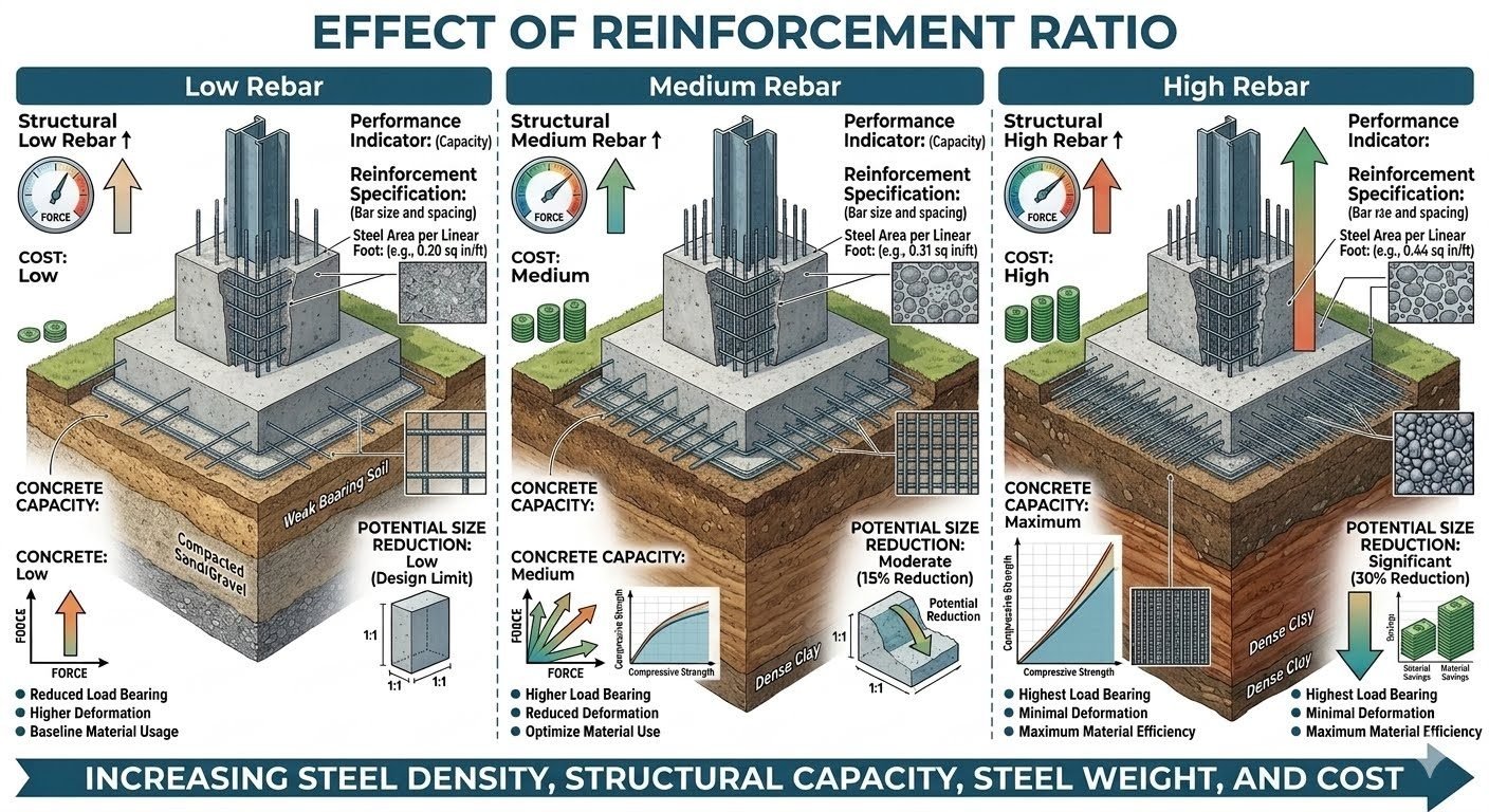
Effect of reinforcement ratio on structural capacity, steel weight, and cost across low, medium, and high rebar densities

Effect of Reinforcement Ratio on Structural Capacity and Size Reduction

Structural Reinforcement Ratio Analysis: Evaluating how varying steel density across low, medium, and high rebar configurations directly governs load-bearing capacity, material efficiency, and structural size reduction limits in compliance with ASCE and ACI 318 standards.

In my two decades of reviewing heavy industrial and structural design packages, I have consistently observed that the steel reinforcement ratio remains the single most influential variable governing member cross-sectional dimensions and cost efficiency. When we evaluate structural elements under heavy bending and axial loads, the precise distribution of steel area per linear foot dictates whether a concrete section operates in a tension-controlled, transition, or compression-controlled domain.

Understanding the distinct thresholds between low, medium, and high rebar configurations allows lead engineers to optimize material usage without compromising safety margins. This technical review examines how shifting from 0.20 sq in/ft to 0.44 sq in/ft impacts ultimate moment capacity, deflection characteristics, and member sizing potential.

Key Engineering Takeaways

  • Low Rebar (0.20 sq in/ft): Delivers minimal cost alongside low structural capacity and negligible size reduction limits.
  • Medium Rebar (0.31 sq in/ft): Achieves balanced performance with a moderate 15 percent potential cross-sectional size reduction.
  • High Rebar (0.44 sq in/ft): Maximizes load-bearing and material efficiency, unlocking a substantial 30 percent potential size reduction.
  • Economic Parallel: Increasing steel density mirrors concrete strength upgrades by directly trading material volume for spatial compactness.
Interactive Engineering QuizEPCLAND Portal
Question 1 of 3

What is the typical steel area specification for a low rebar configuration per linear foot?

Effect of Reinforcement Ratio Mechanics and Design Limits

Reinforcement Ratio Mechanics: Quantifying the mechanical interaction between longitudinal steel area, neutral axis depth, and nominal flexural strength governed by ACI 318 strength design provisions.

The structural reinforcement ratio, denoted mathematically as rho (rho = As / (b · d)), dictates the percentage of total cross-sectional area dedicated to tensile steel reinforcement. In my design practice, controlling this parameter is essential for satisfying both ultimate limit states (ULS) and serviceability limit states (SLS). As we scale steel density from low to high configurations, the internal couple formed by the concrete compressive block and the tensile steel shifts significantly.

To evaluate the true impact of rebar distribution, we must analyze three distinct operating tiers defined by steel area per linear foot:

  • Low Rebar Configuration (0.20 sq in/ft): Operates near minimum reinforcement limits (ACI 318 Section 9.6). It yields a shallow neutral axis depth, resulting in low overall structural capacity, higher deflection under service loads, and virtually zero potential for member size reduction.
  • Medium Rebar Configuration (0.31 sq in/ft): Represents a balanced industrial baseline. This configuration provides moderate concrete capacity, controls flexural cracking within allowable crack width parameters, and enables a moderate 15 percent potential reduction in member cross-sectional dimensions.
  • High Rebar Configuration (0.44 sq in/ft): Pushes steel density toward congestion limits. It maximizes ultimate load-bearing capacity, minimizes long-term creep and deflection, and unlocks a maximum 30 percent potential size reduction, conserving valuable footprint in congested process units.

Critical Design Warning: Steel Congestion and Bond Failure

Exceeding practical reinforcement ratios in high rebar configurations without proper bar spacing risks severe honeycombing and loss of bond strength. Ensure clear spacing complies with ACI 318 minimum bar spacing rules (greater than db, 1 inch, or 1.33 times the maximum aggregate size) to prevent structural failure during concrete consolidation.

From a mathematical perspective, nominal flexural strength (Mn) is calculated using the internal lever arm between the resultant compressive force in the concrete (C = 0.85 · f’c · a · b) and the tensile force in the steel (T = As · fy). When we increase the reinforcement ratio from low to high:

  • The tensile force (T) increases proportionally with steel area (As).
  • The depth of the equivalent rectangular stress block (a) increases to maintain internal equilibrium (a = (As · fy) / (0.85 · f’c · b)).
  • The neutral axis depth (c = a / β_1) deepens, reducing the net tensile strain in the extreme tension steel and pushing the section closer to the tension-controlled strain limit of 0.005.

This direct interaction explains why high rebar configurations achieve superior structural performance. By concentrating high tensile capacity into a smaller concrete profile, structural engineers achieve significant dimensional savings. However, this demands rigorous detailing to ensure ductility is maintained and brittle compression failures are strictly avoided.

Advantages & Disadvantages
Comparative Evaluation: Weighing the structural efficiency, economic investment, and constructability trade-offs across low, medium, and high reinforcement ratio configurations.

Advantages of Optimized Reinforcement

  • High Rebar Efficiency: Achieves up to a 30 percent reduction in structural member dimensions, saving valuable plant footprint.
  • Cost Flexibility: Low rebar configurations (0.20 sq in/ft) minimize initial material expenditure for lightly loaded secondary structures.
  • Deflection Control: Medium and high rebar densities significantly restrict long-term creep and immediate elastic deflections under heavy industrial loads.
  • Crack Mitigation: Increased steel area distributes tensile stresses more evenly, reducing maximum crack widths in aggressive chemical environments.
  • Load Capacity Scaling: Predictable linear scaling allows engineers to tailor member capacity precisely to specific operational load envelopes.

Disadvantages & Technical Risks

  • Congestion Risks: High rebar configurations (0.44 sq in/ft) create severe reinforcement congestion, complicating concrete placement and vibration.
  • Ductility Reduction: Higher steel ratios reduce net tensile strain, shifting the section closer to a brittle compression-controlled failure mode if over-reinforced.
  • Material Cost Escalation: High rebar density substantially increases raw steel material procurement and fabrication expenses per linear foot.
  • Low Capacity Limits: Low rebar configurations severely restrict structural capacity and eliminate potential size reduction, requiring bulkier concrete sections.
  • Thermal Cracking: Dense reinforcement webs increase restraint against early thermal shrinkage, raising the risk of restrained concrete cracking.
Real-World Applications
Industrial Deployment: Practical engineering implementations of varying reinforcement ratios across heavy process plants, infrastructure foundations, and containment structures.

Heavy Pipe Rack Foundations

Industrial pipe racks carrying large-diameter process headers require high structural capacity to resist sustained dead loads, thermal expansion friction, and seismic forces. Utilizing a high rebar configuration (0.44 sq in/ft) enables structural engineers to reduce foundation pad footprints by up to 30 percent, fitting complex underground utility layouts without spatial interference.

Secondary Containment Bunds

Chemical storage tank containment walls experience moderate hydrostatic pressures and thermal cycling. A medium rebar configuration (0.31 sq in/ft) provides an optimal balance between crack control and cost, limiting crack widths to prevent chemical seepage while avoiding the severe reinforcement congestion associated with higher steel ratios.

Lightweight Equipment Pedestals

Minor pump and instrument skids with minimal static loads do not warrant heavy steel investments. Applying a low rebar configuration (0.20 sq in/ft) satisfies minimum temperature and shrinkage steel requirements under ACI 318, achieving low structural capacity at minimal cost where spatial reduction is not required.

Vibration-Prone Compressor Foundations

Reciprocating compressors generate dynamic vibrational loads that require rigid, high-mass concrete blocks combined with dense internal reinforcement. High rebar configurations restrict microscopic deflections and prevent fatigue cracking at anchor bolt assemblies, ensuring long-term alignment stability under continuous cyclic operation.

Elevated Concrete Transfer Slabs

Multi-story industrial modules often rely on thick transfer slabs to redistribute column loads across irregular grid lines. High reinforcement ratios are mandatory in these high-shear zones to achieve maximum load-bearing efficiency, preventing punching shear failures and enabling sleek architectural profiles despite massive tributary loads.

Engineering Data Table: Rebar Configuration Performance Matrix

Evaluating structural performance requires systematic comparison of steel density, cost, and load capacity across varying rebar configurations. The data below synthesizes key parameters governed by ACI 318 provisions for reinforced concrete members.

In my structural design practice, I utilize these baseline metrics to balance material efficiency against serviceability deflection limits under sustained dead and live loads.

Configuration Steel Area (sq in/ft) Relative Cost Structural Capacity Size Reduction
Low Rebar 0.20 Low Low (Design Limit) 0% (Baseline)
Medium Rebar 0.31 Moderate Medium Capacity 15% Reduction
High Rebar 0.44 High Maximum Bearing 30% Reduction

Note: Values reflect standard flexural reinforcement ratios in normal-weight concrete complying with ASTM A615 Grade 60 rebar specifications.

Technical Mapping & Specifications Matrix

Advanced structural engineering relies on precise mapping of physical parameters, governing standards, and material classifications. This entity matrix correlates steel reinforcement variables with international design codes.

Cross-referencing these entities ensures compliance with structural integrity requirements and helps mitigate failure modes during extreme loading events.

Entity / Parameter Standard Reference Design Function Operational Impact
Steel Reinforcement Ratio ACI 318-19 Governs tensile resistance Determines ductility and crack control
Deformed Steel Bars ASTM A615 Grade 60 Provides yield strength Ensures predictable plastic deformation
Concrete Compression ASTM C39 Resists compressive stress Defines member cross-sectional size
Minimum Cover Depth ISO 1920-7 Protects rebar corrosion Ensures long-term structural durability
Site Verification Checklist: Rebar Deployment and Reinforcement Ratio Audit

Reinforcement ratio verification: Validating steel area ratios on-site requires rigorous adherence to design drawings and structural specifications. Ensuring correct rebar placement prevents premature structural distress.

I mandate this verification protocol on all major industrial projects to reconcile theoretical calculations with actual fabricated steel density before concrete placement.

Field Inspection Verification Steps

  • [ ] Bar Spacing Check: Measure clear distances between parallel reinforcing bars to confirm compliance with ACI 318 aggregate clearance rules.
  • [ ] Steel Area Verification: Cross-check delivered rebar size and count against structural schedules to verify target sq in/ft ratios.
  • [ ] Lap Splice Lengths: Inspect tension and compression lap splice lengths to ensure adequate load transfer across joints.
  • [ ] Cover Maintenance: Verify chair and spacer placement to maintain specified concrete cover against environmental corrosion.
  • [ ] Ductility Validation: Confirm grade markings on steel bars match structural calculations requiring ductile failure behavior.

Completion of every checkpoint must be signed off by the quality control inspector and logged in the permanent project quality management system.

Field Case Study: Real-World Application

Case study analysis: Examining a high-load industrial foundation retrofit project reveals critical insights into reinforcement ratio selection. The structure experienced unexpected settlement and flexural cracking under increased equipment loads.

The Problem Encountered

Initial low rebar configurations resulted in excessive deflection and premature structural distress under heavy dynamic machinery.

  • Reinforcement density was restricted to 0.20 sq in/ft, failing to resist cyclical fatigue loads.
  • Excessive cracking compromised serviceability limits outlined in ACI 318.
  • Member thickness could not be reduced, adding dead weight to already overburdened soil foundations.
  • Maintenance interventions became frequent, causing costly plant downtime.

The Solution & Outcome

Transitioning the design to a high rebar configuration successfully restored structural integrity and enabled significant member optimization.

  • Increased steel area to 0.44 sq in/ft, maximizing load-bearing capacity and fatigue resistance.
  • Achieved a 30% reduction in structural member size, lowering overall foundation dead load.
  • Eliminated serviceability cracking and extended operational lifespan without exceeding budget constraints.
  • Maximized material efficiency and compliance with strict industrial safety standards.

Recommendation: For high-demand industrial foundations, always evaluate high rebar configurations during early design phases to leverage size reduction benefits and prevent costly retrofits later.

Frequently Asked Engineering Questions

What is the typical steel area specification for a low rebar configuration?
A low rebar configuration generally utilizes approximately 0.20 square inches of steel area per linear foot, prioritizing minimal upfront material costs over high load-bearing capacity. Engineers typically specify this baseline ratio for lightly loaded non-structural elements where space constraints are absent.
  • Steel Area: Approximately 0.20 sq in/ft along the primary tension face.
  • Cost Impact: Minimizes initial rebar procurement expenses on budget-sensitive projects.
  • Design Constraint: Exhibits low potential size reduction and lower overall structural capacity.
How does a medium rebar setup balance cost and structural performance?
A medium rebar setup provides a balanced approach by supplying roughly 0.31 square inches of steel per linear foot to achieve moderate capacity at a predictable budget. This configuration serves as a reliable baseline for standard commercial floor slabs and foundation walls governed by ACI 318 provisions.
  • Steel Area: Approximately 0.31 sq in/ft for balanced tensile resistance.
  • Efficiency: Delivers a moderate 15% potential size reduction for structural elements.
  • Application Balance: Offers an optimal compromise between material expense and section depth.
What structural advantages do high rebar configurations provide?
High rebar configurations utilize approximately 0.44 square inches of steel per linear foot to maximize load-bearing capacity, minimize deflections, and achieve significant geometric footprint reductions. By packing denser reinforcement into the concrete matrix, designers can safely reduce overall member dimensions under heavy industrial loads.
  • Steel Area: Approximately 0.44 sq in/ft providing maximum tensile reinforcement.
  • Geometric Advantage: Enables up to a 30% potential size reduction in structural thickness.
  • Performance: Minimizes structural deformation and crack widths under severe loading states.
How does reinforcement ratio scaling parallel concrete strength grade adjustments?
Increasing steel reinforcement density parallels upgrading concrete compressive strength in its ability to reduce member sizing, though through tensile steel capacity rather than compressive matrix strength. Both methodologies allow engineers to optimize spatial footprints by trading raw material costs for structural density.
  • Mechanism Parallel: Steel density controls tensile capacity much like concrete strength controls compression.
  • Spatial Optimization: Both approaches achieve member size reductions to clear architectural obstructions.
  • Cost Correlation: Higher performance tiers in both steel and concrete escalate material unit costs.
What design limits govern maximum rebar density in concrete sections?
Structural codes enforce strict maximum reinforcement ratios to prevent sudden, brittle compression failures and ensure adequate aggregate consolidation around congested rebar cages. When pushing toward high rebar configurations, rebar spacing and clear cover requirements must be meticulously detailed.
  • Code Compliance: Adherence to maximum steel percentage limits per ASCE and ACI standards.
  • Placement Clearance: Ensuring proper aggregate flow and consolidation through tight rebar spacing.
  • Ductility Assurance: Maintaining ductile steel yielding behavior prior to concrete crushing.

Field Recommendation

Based on my two decades of industrial design experience, selecting the correct reinforcement ratio requires balancing spatial constraints against procurement budgets. Here are my specific field recommendations for structural engineers:

  • Choose Low Rebar (0.20 sq in/ft) only for lightly loaded, non-structural slabs-on-grade or temporary trench caps where budget is strictly constrained and subsequent structural alterations are not anticipated.
  • Specify Medium Rebar (0.31 sq in/ft) as your default baseline for standard commercial foundation walls and elevated slabs to achieve a reliable 15 percent size reduction without creating rebar congestion issues.
  • Implement High Rebar (0.44 sq in/ft) whenever architectural clearances demand a 30 percent sectional size reduction, ensuring that aggregate size and slump are strictly monitored to prevent honeycombing in congested cages.
  • Perform Clash Detection on all high-density rebar configurations during the 3D modeling phase to verify that lap splices, anchor bolts, and embedments do not interfere with concrete placement.

Complete Course on
Piping Engineering

Check Now

Key Features

  • 125+ Hours Content
  • 500+ Recorded Lectures
  • 20+ Years Exp.
  • Lifetime Access

Coverage

  • Codes & Standards
  • Layouts & Design
  • Material Eng.
  • Stress Analysis
Atul Singla - Piping EXpert

Atul Singla

Senior Piping Engineering Consultant

Bridging the gap between university theory and EPC reality. With 20+ years of experience in Oil & Gas design, I help engineers master ASME codes, Stress Analysis, and complex piping systems.