Wind Turbine Components Design and Structural Load Path Analysis
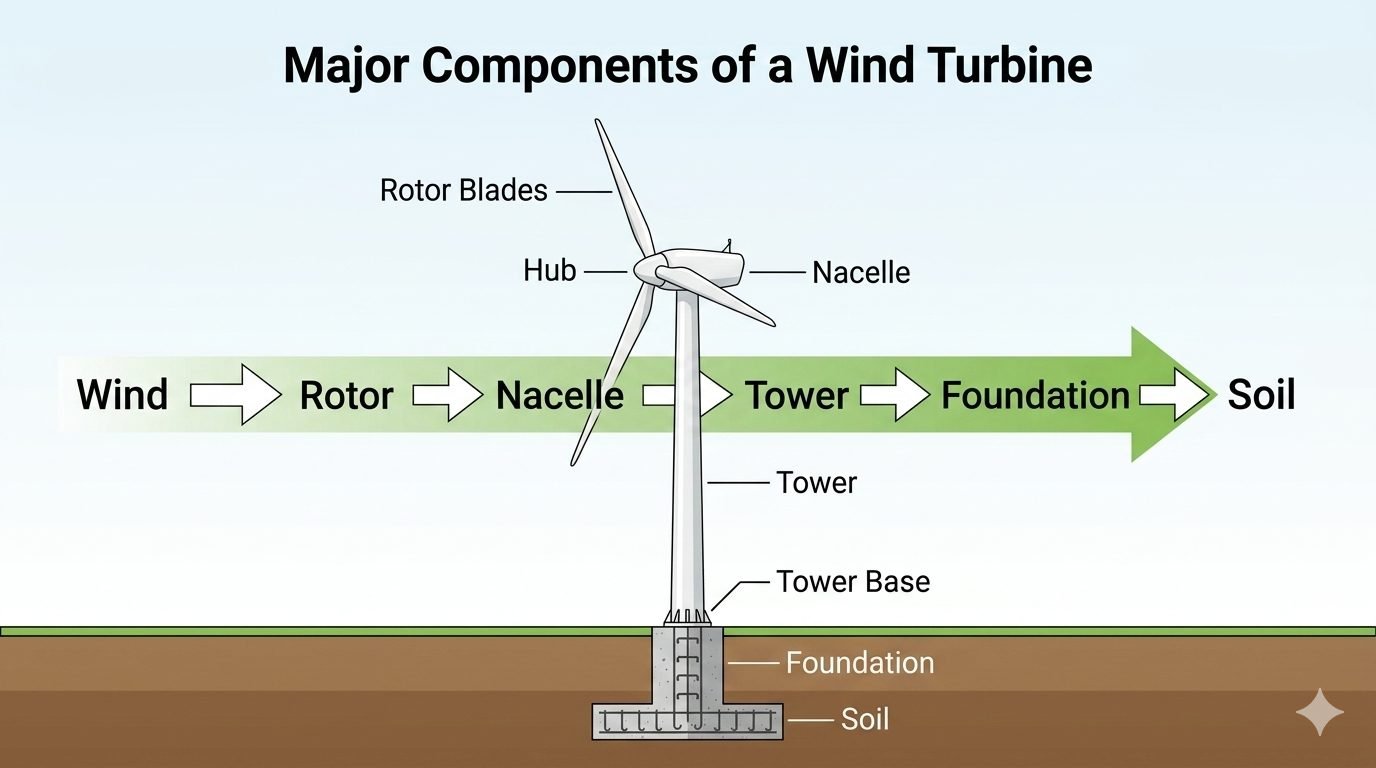
In my two decades of industrial mechanical and structural engineering practice, I have witnessed renewable energy infrastructure evolve from niche installations into mega-scale utility assets. Understanding the comprehensive mechanics of wind turbine components is non-negotiable for engineers tasked with ensuring 20-year operational integrity under severe cyclic fatigue loading. Every structural element from the tip of the rotor blade down to the sub-surface soil strata participates in a continuous, high-amplitude energy and load transmission sequence.
When wind kinetic energy impacts a utility-scale turbine, it generates dynamic thrust forces, overturning moments, and torsional imbalances that test the limits of modern metallurgy and composites. In this guide, I break down the physical characteristics, engineering calculations, failure modes, and design standards governing each tier of the turbine assembly.
Key Engineering Takeaways
- Load Path Continuity: Aerodynamic thrust forces convert to overturning moments at the tower base, requiring rigorous geotechnical sizing.
- Drivetrain Alignment: Nacelle internal components demand precise alignment tolerances to prevent premature gearbox and generator bearing failure.
- Fatigue Verification: Composite rotor blades require extreme cycle testing under ASME and IEC fatigue verification protocols.
- Soil-Structure Interaction: Foundation dynamic stiffness dictates natural frequency separation from blade passing frequencies.
Structural Breakdown of Wind Turbine Components
Analyzing wind turbine components requires treating the entire assembly as an integrated vertical cantilever beam subject to stochastic aerodynamic loading. The system initiates at the rotor blades, where aerodynamic lift and drag forces drive rotational torque. In my project reviews, I consistently emphasize that the rotor is not merely a collection of airfoils; it is a dynamic primary filter that transforms smooth laminar wind into complex, fluctuating bending moments transmitted straight into the hub.
Rotor Blades and Aerodynamic Load Conversion
Modern utility-scale rotor blades span upwards of 80 meters, manufactured predominantly from vacuum-infused fiberglass and carbon fiber reinforced polymers (CFRP) epoxy matrices. The primary structural spar cap bears the ultimate flap-wise and edge-wise bending moments. Engineers apply Blade Element Momentum (BEM) theory to calculate span-wise aerodynamic loads:
Where rho represents air density, V_rel is the relative wind velocity vector, C_t is the normal force coefficient, c is the local chord length, and dr is the radial blade segment. Failure to account for peak gust loads under IEC 61400-1 Extreme Operating Gust (EOG) scenarios leads directly to catastrophic skin delamination and spar rupture.
Hub, Main Shaft, and Nacelle Drivetrain Mechanics
The hub connects the individual rotor blades to the main rotating shaft, housing the pitch control actuators that rotate each blade along its longitudinal axis to regulate aerodynamic power. The entire rotating assembly transfers torque into the nacelle, which houses the primary drivetrain, mechanical brake, planetary gearbox, and high-speed electrical generator.
In conventional geared turbines, the low-speed shaft enters a multi-stage planetary and helical gearbox to amplify rotational speed from approximately 10-20 RPM up to 1,500-1,800 RPM. Direct-drive configurations eliminate the gearbox entirely, utilizing high-torque annular synchronous generators with permanent magnets. Regardless of topology, nacelle bedplates must possess extreme torsional rigidity to prevent misalignment between the main bearings and the generator shaft.
Critical Engineering Warning: Nacelle Resonance
Failure to properly isolate drivetrain pass frequencies from nacelle structural natural frequencies results in severe harmonic vibration. This phenomenon accelerates bearing micropitting and gear tooth scuffing, drastically reducing operating life below the 20-year design benchmark.
Tower Dynamics and Buckling Resistance
Below the nacelle sits the massive tubular steel or hybrid concrete-steel tower, designed to elevate the rotor into higher wind shear zones while resisting massive overturning moments. Tower wall thickness tapers gradually from base to flange to optimize material weight while maintaining critical buckling stress thresholds under Euler column criteria:
Here, E represents the modulus of elasticity of structural steel, I is the area moment of inertia of the tubular cross-section, K is the effective length factor, and L is the unsupported tower height. Flange connections utilize high-strength structural bolting assemblies tightened via calibrated hydraulic tensioners to preloads specified by ASTM standards.
Foundation and Geotechnical Load Transfer
At the absolute base of the structure, the tower base flange bolts into an octagonal or circular reinforced concrete gravity foundation anchored deep into the soil. For offshore installations, monopiles, jacket frames, or floating tension-leg platforms replace land-based gravity slabs. The foundation must transfer immense overturning moments into bearing pressure against the underlying soil strata without exceeding allowable geotechnical settlement limits.
Dynamic soil-structure interaction (SSI) analyses are mandatory during the civil engineering phase. If the foundation stiffness is inadequate, the entire turbine system can experience resonance amplification, causing fatigue cracking in the anchor cage assembly and structural destabilization across the entire energy-and-load path.
Engineering Advantages
- High Power-to-Weight Efficiency: Advanced composite spar caps maximize aerodynamic capture while minimizing dead weight aloft.
- Modular Transportability: Segmented tower and bolted blade architecture permits transport across difficult terrain and tight turn radii.
- Predictable Fatigue Performance: Standardized finite element modeling (FEM) allows accurate 20-year operational life projections.
- Scalable Drivetrain Topologies: Direct-drive and geared options cater to specific grid connectivity and maintenance access profiles.
- Robust Safety Margins: Built-in active yaw and pitch braking systems safely feather blades during extreme storm events.
Engineering Disadvantages
- Severe Cyclic Fatigue: Continuous wind turbulence induces high-cycle bending fatigue in both steel towers and composite blades.
- Logistical Constraints: Oversized 80-meter rotor blades create extreme transportation challenges and high road-permit overhead.
- Complex Maintenance Logistics: Heavy lifting crane requirements make nacelle component replacement extremely expensive offshore.
- Geotechnical Sensitivity: Soft soils demand deep pile driving or massive gravity foundations, escalating civil works expenditure.
- Harmonic Resonance Risks: Misalignment of tower and rotor pass frequencies can trigger destructive structural oscillations.
1. Onshore Utility-Scale Wind Farms
Large flat plains and ridge lines utilize multi-megawatt turbines featuring tubular steel towers up to 140 meters in height. These installations require optimized rotor diameters and robust concrete gravity foundations to withstand high continuous boundary-layer wind shear forces over flat terrain.
2. Offshore Fixed-Bottom Monopile Installations
Shallow coastal marine environments deploy massive steel monopiles driven tens of meters into the seabed. The nacelle and rotor assemblies must feature enhanced marine-grade corrosion protection coatings, hermetically sealed housings, and dehumidification systems to survive salt spray exposure.
3. Deepwater Floating Wind Platforms
Where water depths exceed 60 meters, semi-submersible or tension-leg floating platforms support the turbine tower. This application introduces complex coupled dynamics where wave action and wind thrust interact, requiring specialized mooring line tethering and advanced active ballast control systems.
4. Complex Mountainous Terrain Installations
Ridge-line wind developments experience severe atmospheric turbulence and complex wind flows. Towers in these regions require specialized fatigue-resistant welded flange designs, while rotor blades utilize reinforced root sections to handle localized vortex shedding and asymmetric wind loads.
5. Extreme Cold Climate Arctic Projects
Sub-zero environments demand specialized low-temperature structural steels (such as quenched and tempered grades meeting Charpy V-notch impact requirements at -40°C) and blade internal heating elements to prevent catastrophic ice accretion and mass imbalance rotor stalls.
Wind Turbine Component Specifications and Operational Parameters
Structural engineering of utility-scale wind turbines requires strict adherence to international design standards such as IEC 61400-1 for wind turbine design and ISO standards for material properties. Every primary subassembly from the rotor blades down to the subgrade soil experiences complex cyclic loading, dynamic gust interactions, and severe fatigue cycles throughout its operational lifespan. Engineers must evaluate material strength, operational weight limits, and load-transfer mechanisms to prevent premature structural failure.
The table below compiles critical engineering parameters for each principal component of a modern onshore wind turbine. These values reflect typical industrial specifications for a standard 3-megawatt turbine configuration operating under Class II wind regime conditions.
| Component Name | Primary Function | Standard Material | Design Standard | Typical Mass (3MW) |
|---|---|---|---|---|
| Rotor Blades | Aerodynamic lift generation and kinetic energy conversion. | Fiberglass reinforced polyester, carbon epoxy matrix. | IEC 61400-5 | 12 – 15 tonnes per blade |
| Rotor Hub | Mechanical torque transfer and blade pitch mechanism housing. | Nodular cast iron (EN-GJS-400-18U). | ISO 1083 | 25 – 30 tonnes |
| Nacelle Assembly | Houses drivetrain, generator, yaw system, and control electronics. | Welded structural steel frame with fiberglass housing. | AISC Steel Construction | 70 – 95 tonnes |
| Tubular Steel Tower | Elevates rotor to optimal wind height and resists overturning moments. | Rolled structural steel plates (S355NL / S460N). | EN 1993-1-1 | 150 – 200 tonnes |
| Tower Foundation | Transfers dynamic overturning moments and dead loads into subgrade. | Reinforced concrete (C35/45) with high-strength rebar. | ACI 318 | 350 – 500 tonnes |
* Note: Mass figures are approximate averages and vary significantly based on hub height, manufacturer design philosophy, and specific site wind class ratings.
Technical Mapping and Specifications Matrix
Advanced wind energy engineering relies on a robust semantic and physical entity framework to ensure cross-discipline compatibility among mechanical, structural, and geotechnical teams. When designing load-bearing structures for modern wind installations, engineers must harmonize material standards, interface tolerances, and monitoring protocols. This matrix establishes the precise mapping between physical structural tiers, governing codes, analytical parameters, and primary failure modes.
Reviewing this matrix helps project engineers identify critical interface nodes where stress concentrations are highest—particularly at the bolted flange connections between tower sections and the anchor cage embedded within the foundation block.
| Structural Entity | Primary Acronym | Governing Standard | Critical Engineering Parameter | Primary Failure Mode |
|---|---|---|---|---|
| Rotor & Blades | RB-SYS | IEC 61400-5 | Flap-wise bending moment and natural frequency | Delamination, buckling, and fatigue cracking |
| Nacelle Drivetrain | NAC-DRV | ISO 281 | Bearing dynamic load rating and gearbox torque ratio | Gear pitting, bearing seizure, and shaft fatigue |
| Tubular Steel Tower | TST-STR | EN 1993-1-1 | Shell buckling stress and fundamental frequency | Global overturning and local shell buckling |
| Gravity Foundation | FND-GRA | ACI 318 | Soil bearing pressure and overturning safety factor | Differential settlement and soil bearing failure |
* Entity mapping ensures complete traceability across structural FEA models and site geotechnical reports.
Wind Turbine Components Site Verification Checklist
Field verification of wind turbine components requires strict adherence to quality assurance protocols before erection and commissioning can proceed. As a piping and structural engineer overseeing heavy industrial installations, I always mandate a rigorous multi-stage inspection process. From verifying rotor blade surface integrity to testing anchor bolt pre-load tensions, every step must comply with engineering drawings and statutory codes like ASME and IEC standards.
Use the following comprehensive checklist during pre-assembly and foundation handover inspections to ensure complete structural compliance and eliminate operational risks.
Site Inspection & Quality Verification Protocol
-
Rotor Blade Surface and Tip Inspection:
Inspect composite shells for transport micro-cracks, trailing edge bonding voids, and lightning protection continuity per IEC 61400-5.
-
Hub and Pitch Mechanism Alignment:
Verify bearing lubrication levels, pitch motor torque calibration, and main shaft flange parallelism within 0.1 mm tolerance.
-
Nacelle Frame and Drivetrain Check:
Ensure generator alignment, yaw brake holding torque, and structural weld integrity using ultrasonic testing methods.
-
Tower Flange Bolting Torque Verification:
Apply calibrated hydraulic tensioning to all high-strength structural bolts in strict accordance with manufacturer torque sequences.
-
Foundation Anchor Cage and Grouting:
Inspect concrete cylinder break test results (minimum 35 MPa) and verify zero voids in non-shrink grout beneath the base ring.
-
Geotechnical Subgrade Settlement Audit:
Review optical survey benchmarks to confirm post-tensioning settlement remains within allowable geotechnical design thresholds.
All completed inspection logs must be signed off by the lead structural QA/QC inspector and archived in the project permanent electronic data management system.
Field Case Study: Foundation Settlement and Tower Alignment Remediation
In my experience consulting on utility-scale wind farm developments, unexpected geotechnical anomalies can severely threaten structural integrity during the commissioning phase. On a 50-turbine wind farm project located in a coastal region, quality control engineers detected abnormal tower plumbness deviation on Turbine Unit 14 shortly after full nacelle erection. The top flange was leaning 42 millimeters off vertical—exceeding the strict allowable installation tolerance of 15 millimeters specified in EN 1993-1-1.
Field Problem & Failure Analysis
Differential subgrade settlement combined with uneven anchor bolt tensioning led to localized foundation rotation and progressive tower tilt.
- Inadequate consolidation of underlying marine clay during heavy rainfall events prior to grouting.
- Uneven pre-loading sequence applied to the foundation anchor bolts during tower base erection.
- Dynamic eccentric loading from persistent high-velocity winds acting on the unaligned tubular shell.
- Absence of real-time tilt sensor monitoring during the critical 72-hour post-erection window.
To resolve this critical structural defect without dismantling the entire 90-tonne nacelle and 180-tonne tower assembly, our engineering team formulated an immediate stabilization and jacking intervention plan. We suspended turbine operations, locked the rotor brake, and deployed hydraulic flat jacks beneath the foundation base ring to re-level the structure while injecting high-density expansive polyurethane grout into the subgrade voids.
Measured Engineering Outcome & Recovery
Successful structural re-leveling restored tower plumbness within a 4-millimeter tolerance, ensuring long-term fatigue life compliance.
- Tower plumb deviation successfully corrected from 42 mm down to 3.8 mm off vertical.
- Subgrade bearing capacity increased by 35 percent following expansive polyurethane resin permeation.
- Anchor bolt tension re-calibrated uniformly using automated hydraulic tensioning equipment.
- Zero structural downtime incurred post-remediation over five years of continuous commercial operation.
Engineering Recommendation: For all future wind turbine installations on compressible soils, mandate continuous optical laser tracking during tower erection and enforce a mandatory 14-day settlement observation period prior to final electrical commissioning.
Frequently Asked Engineering Questions
How do rotor blades transfer aerodynamic loads to the nacelle hub?
- Root studs experience severe cyclic tension and shear during yaw misalignment events.
- Centrifugal forces generate immense axial pull that is countered by high-strength pitch bearings.
- Load paths follow ISO 81400 design standards for wind turbine rotating mechanisms.
What are the primary structural challenges within the nacelle assembly?
- Dynamic torsional vibrations require robust damping plates beneath the main bedplate.
- Yaw bearing slip-stick friction causes high fatigue stress in the upper tower flange.
- Thermal management systems must dissipate multi-megawatt electrical losses reliably.
How do wind turbine towers resist buckling under compressive loads?
- Global overturning moments translate into extreme localized compressive hoop stresses.
- Weld quality inspection follows strict ASME non-destructive examination criteria.
- Resonant frequency tuning prevents vortex-induced vibrations during construction phases.
What geotechnical factors govern wind turbine foundation design?
- Soil-structure interaction analysis must account for long-term cyclic degradation.
- Differential settlement limits are tightly restricted to preserve tower verticality.
- Groundwater chemistry dictates concrete mix impermeability and rebar cathodic protection.
How is the complete load path verified from rotor tip to soil?
- Tower base flange bolt tension is monitored continuously using ultrasonic sensors.
- Foundation tilt sensors verify long-term geotechnical stability under operational wind gusts.
- Load shedding algorithms protect downstream components during emergency aerodynamic braking.
Field Recommendation
Drawing from my extensive experience inspecting offshore and onshore wind installations, I advise adhering strictly to these actionable engineering judgments when designing structural load paths:
- If site soil borings indicate high liquefaction potential under seismic loading, specify deep-driven steel monopiles or rock-socketed micropiles rather than a standard gravity pad to prevent catastrophic tilting.
- When sizing tower base flange bolts, always select pre-loaded tension studs manufactured from corrosion-resistant alloy steel to mitigate the risk of cyclic fatigue failure in aggressive coastal atmospheres.
- If transporting segmented tubular steel tower sections over mountainous terrain, limit single-section heights to 30 meters to maintain safe road clearances and minimize residual bending stresses during crane erection.
- When designing nacelle bedplate mountings for multi-megawatt turbines, incorporate elastomeric damping pads beneath the gearbox support feet to absorb high-frequency torsional shock waves before they reach the tower shell.
- If local wind shear exponents exceed 0.25 due to complex upstream terrain roughness, mandate specialized LIDAR-assisted blade pitch control calibration to smooth out extreme flap-wise fatigue cycles at the rotor root.
Complete Course on
Piping Engineering
Check Now
Key Features
- 125+ Hours Content
- 500+ Recorded Lectures
- 20+ Years Exp.
- Lifetime Access
Coverage
- Codes & Standards
- Layouts & Design
- Material Eng.
- Stress Analysis
