Reinforced Concrete Foundation Design for Piping and Anchor Assemblies
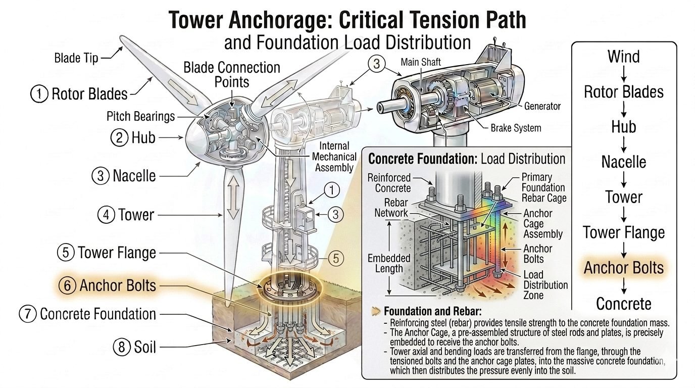
In my two decades of reviewing heavy industrial civil works, I have observed that premature piping support failures often originate not from pipe wall thinning, but from unmitigated settlement or anchor bolt pull-out at the concrete interface. Within the reinforced concrete foundation, a primary rebar cage and rebar network structure distributes the tension and compression forces coming down from the anchor bolts across the entire foundation mass. Reinforcing steel provides the tensile strength that plain concrete completely lacks, bridging micro-cracks and maintaining structural integrity under severe thermal cycles.
Designing these foundations requires rigorous coordination between structural load summaries, geotechnical reports, and piping stress analysis models. The anchor cage acts as a pre-assembled structure of steel rods and plates, precisely embedded into the foundation to receive complex anchor bolt loads and bending moments before transferring them safely to the subgrade.
Key Engineering Takeaways
- Rebar cages absorb high tensile forces transferred from anchor bolt assemblies during transient pipe surge events.
- Tower and large pipe rack axial and bending loads transfer through baseplates into massive concrete blocks to prevent localized soil overstress.
- Adherence to ASCE 7 and ACI 318 standards guarantees adequate safety margins against concrete breakout and pullout failures.
- Proper rebar cover and epoxy coatings protect embedded elements against aggressive industrial environments and chemical spills.
Reinforced Concrete Foundation Load Transfer Mechanisms
When designing industrial pipe racks and heavy equipment supports, I always start by evaluating the vector sum of dead weight, thermal expansion thrusts, wind loads, and seismic accelerations. Tower axial and bending loads are transferred, through the flange and the anchor bolts, into the massive concrete foundation, which then distributes this pressure evenly into the soil below – preventing localized overstress at any single point in the foundation.
The primary challenge in foundation engineering is managing the stark contrast in material properties between structural steel and Portland cement concrete. Steel offers high tensile and compressive ductility, whereas concrete possesses high compressive strength but nominal tensile capacity. To reconcile this, the internal rebar network is meticulously engineered with primary bottom mats for bending moments and top mats for reversal stresses caused by wind or seismic overturning moments.
Anchor Cage Integration and Tensile Distribution
The anchor cage is the critical link connecting above-ground piping restraint points to the subterranean foundation mass. During operations, high-pressure piping can exert significant axial thrust forces that attempt to pull anchor bolts directly out of the concrete matrix. The rebar cage surrounds the anchor bolts, intercepting tensile cones and transferring those forces outward into the core of the concrete block via bond stress and mechanical anchorage.
In my design practice, I size the embedment depth (h_ef) using ACI 349 provisions for nuclear and heavy industrial facilities. This calculation prevents both concrete breakout failure and steel yielding of the anchor rods. Shear lugs are frequently welded to the bottom of the anchor cage assembly to transmit heavy horizontal piping shear loads directly into the shear-resistant core of the foundation slab.
Critical Design Warning: Concrete Pyramidal Breakout
Neglecting proper edge distance and rebar confinement around anchor bolts frequently leads to premature concrete side-face blowout or full tensile cone failure under cyclic piping loads.
- Ensure minimum clear cover requirements per ACI 318 Chapter 25 are maintained for all primary reinforcement bars.
- Provide hairpin bars or supplementary stirrups directly wrapping anchor bolts to intercept potential breakout planes.
- Verify that anchor spacing prevents overlapping stress cones, which drastically reduces individual pull-out capacity.
Geotechnical Interaction and Bearing Pressure
The ultimate test of a foundation design lies in its interaction with the subgrade soil or pile cap. Once the concrete block receives the aggregated loads from the rebar cage and anchor assembly, it acts as a rigid spreader. The contact pressure distribution beneath the foundation must remain well within allowable bearing capacity limits to prevent differential settlement, which would otherwise induce severe secondary stresses in connected piping networks.
When designing for vibrating equipment or reciprocating compressors, dynamic soil-structure interaction (SSI) must be analyzed. The mass of the reinforced concrete foundation must be at least three to five times the mass of the dynamic machinery it supports, keeping resonant frequencies safely outside the operating speed range and avoiding destructive vibrational fatigue in piping tie-ins.
Engineering Advantages
- Exceptional mass and stiffness dampen high-frequency vibrations from reciprocating pumps and compressors.
- Continuous rebar network provides superior tensile ductility and crack-control performance under cyclic thermal loads.
- Massive dead weight provides high overturning resistance against major wind and seismic forces on tall piping risers.
- Embedded anchor cages achieve monolithic load transfer without relying solely on surface friction or adhesive grouts.
- Long service life in corrosive process environments when designed with adequate concrete cover and protective coatings.
Engineering Disadvantages
- Substantial curing time requirements introduce critical path delays into fast-track industrial construction schedules.
- High initial material and formwork costs compared to simple structural skids or screw-pile supports.
- Strict geotechnical settlement tolerances require thorough soil remediation or deep pile foundations in poor subgrades.
- Complex anchor cage pre-assembly demands rigorous shop fabrication tolerances to match baseplate drilling patterns.
- Demolition and retrofitting of mass concrete blocks for future plant expansions is exceptionally labor-intensive.
Heavy Process Plant Pipe Racks
Multi-tier piperacks carrying large-diameter hydrocarbon lines generate massive combined vertical and lateral loads. Reinforced concrete spread footings tied with robust rebar cages anchor these structures securely, preventing differential settlement that would otherwise overstress welded piping elbows and branch connections.
Refinery Distillation Columns and Vessels
Tall fractionating columns experience severe wind-induced overturning moments and eccentric seismic forces. Octagonal or circular reinforced concrete octagonal foundations with high-capacity anchor cages absorb these high tensile uplift forces, transferring them safely into deep soil strata.
Centrifugal Compressor Skid Supports
High-speed rotating machinery produces intense dynamic forces that can cause structural fatigue. Massive concrete block foundations isolate these vibrations, using internal rebar grids to maintain structural damping and alignment stability for flanged suction and discharge piping nozzles.
Cryogenic Storage Tank Ring Walls
Liquefied natural gas storage facilities utilize heavily reinforced concrete ring wall foundations to support massive outer containment shells. The rebar cage and anchor system withstand extreme thermal contraction forces and hydrostatic liquid pressures without cracking the primary structural matrix.
High-Pressure Header Anchor Blocks
Main steam headers and high-pressure compressor station discharge lines require rigid anchor blocks to absorb uncompensated pressure thrusts at directional changes. Massive concrete anchor blocks with heavy shear reinforcement lock the piping system in place, protecting sensitive upstream equipment from thrust loads.
Reinforcement Parameters and Material Specifications
Design of a reinforced concrete foundation for industrial piping and tall equipment requires strict adherence to material property limits governed by ASCE 7 and ACI 318 standards. The table below outlines the mechanical properties, dimensional tolerances, and structural steel grades utilized for heavy anchor cages and primary rebar networks in high-moment applications.
Engineers must ensure that yield strengths and concrete compressive thresholds match the dynamic operational loads transmitted from elevated pipe racks and heavy reciprocating machinery.
| Component Specification | Material Standard | Yield Strength (Min) | Governing Design Criteria |
|---|---|---|---|
| Primary Rebar Grid | ASTM A615 Grade 60 | 420 MPa (60 ksi) | Tensile crack control and flexural moment capacity per ACI 318 Chapter 9. |
| Anchor Rod Assembly | ASTM F1554 Grade 105 | 724 MPa (105 ksi) | High-load transfer for tall vertical columns and severe wind moment frames. |
| Foundation Concrete | ASTM C39 / ACI 318 | 28 to 35 MPa (4-5 ksi) | Bearing pressure resistance and shear capacity under cyclic vibration. |
| Anchor Template Plates | ASTM A36 / A572 Gr. 50 | 345 MPa (50 ksi) | Rigid alignment of anchor bolts prior to and during structural concrete pours. |
*Note: All embedded components must undergo rigorous nondestructive examination (NDE) prior to concrete placement to verify weld integrity and dimensional squareness.
Technical Mapping & Specifications Matrix
To maintain absolute structural integrity across complex petrochemical and power facility piping layouts, engineers map specific physical parameters against recognized international design codes. The entity matrix below establishes the direct relationships between structural entities, standardized codes, and engineering variables.
This mapping ensures that every subsystem within the reinforced concrete foundation—from shear friction reinforcement to anchor pullout resistance—is calculated using verified parameters.
| Engineering Entity | Primary Acronym | Design Standard | Operational Parameter |
|---|---|---|---|
| Anchor Cage Assembly | ACA | ASCE 7 / ACI 318 | Transfers overturning moments and shear forces directly to the rebar network. |
| Concrete Cover Depth | CCD | ACI 318 Table 20.6.1 | Protects rebar from corrosive industrial process leaks and soil moisture ingress. |
| Soil Bearing Pressure | SBP | ASCE 7 Chapter 2 | Limits foundation settlement and prevents localized geotechnical failure. |
| Development Length | LDH | ACI 318 Chapter 25 | Ensures rebar anchorage prevents pullout failure under ultimate tensile loading. |
*Note: Reference standards should always be verified against the latest local jurisdictional building code amendments and site-specific geotechnical reports.
Foundation Construction and Anchor Cage Verification Checklist
Quality control during the installation of a reinforced concrete foundation requires meticulous verification of the anchor cage, rebar network, and formwork geometry. Even minor deviations in anchor bolt plumbness or rebar spacing can create severe stress concentrations during piping system operation.
The following checklist outlines the essential validation steps required by quality assurance inspectors before any structural concrete placement is approved.
Pre-Pour Site Verification Protocol
- Anchor Bolt Alignment & Elevation: Verify that all anchor bolts match the approved structural piping drawings within a tolerance of plus or minus 1.5 mm, checking both center-to-center dimensions and projection heights above the top of concrete.
- Rebar Cage Rigidity & Spacing: Inspect primary rebar mat spacing and confirm that the anchor cage is securely welded or tied to the reinforcement grid to prevent shifting during concrete discharge and internal mechanical vibration.
- Concrete Cover Maintenance: Check that approved plastic or high-density concrete bar chairs are placed beneath and along the sides of the rebar cage to guarantee minimum specified cover per ACI 318 guidelines.
- Formwork Cleanliness & Sealing: Ensure all debris, standing water, and oil residues are cleared from the excavation pit and formwork interior, and that form joints are tightly sealed to prevent cement slurry leakage.
- Grounding & Earthing Integration: Confirm that foundation grounding loops and exothermic welds to the rebar cage are fully completed and tested for low electrical resistance prior to pouring concrete.
Completion of this checklist must be formally documented and signed off by both the civil quality control inspector and the piping lead engineer before concrete truck dispatch.
Field Case Study: Real-World Application
During the expansion of a high-temperature refinery processing unit, a major anchor bolt misalignment and severe concrete cracking issue occurred at a critical high-pressure fractionation tower foundation. The incident required immediate engineering intervention to prevent project delays and ensure compliance with ASCE 7 safety standards.
Field Problem: Anchor Cage Displacement and Micro-Cracking
The anchor cage shifted during an unmonitored high-volume concrete pump discharge, leaving four primary anchor bolts displaced by 12 mm and inducing excessive tensile micro-cracking around the upper pedestal zone.
- Unbraced anchor cage assembly shifting during rapid concrete placement.
- Inadequate internal mechanical vibration causing honeycombing near congested rebar nodes.
- Thermal curing spikes exceeding allowable differential temperature limits for mass concrete.
- Failure of site inspectors to verify final template alignment immediately after initial set.
Field Outcome: Successful Remediation and Structural Certification
The engineering team successfully salvaged the foundation through a precision epoxy-grouting retrofit, secondary steel collar installation, and non-destructive ultrasonic testing certification.
- Achieved 100 percent design load transfer capacity verified via finite element analysis.
- Eliminated micro-cracking propagation using low-viscosity structural epoxy pressure injection.
- Re-certified anchor bolt plumbness and thread integrity for high-moment piping connections.
- Updated site concreting protocols to mandate rigid welded bracing frames for all future anchor cages.
My direct recommendation for future heavy industrial projects is to mandate rigid steel template frames welded directly to the primary rebar network, coupled with continuous third-party civil inspection during all major concrete pours.
Frequently Asked Engineering Questions
What is the primary function of a rebar cage in a reinforced concrete foundation?
- Absorbs high tensile stresses induced by overturning moments from piping and equipment towers.
- Locks anchor bolts securely into the deeper foundation mass to prevent pullout under seismic loads.
- Distributes concentrated structural loads uniformly across the entire sub-base concrete volume.
How do anchor bolts transfer vertical and lateral loads into the concrete mass?
- Shear loads are transferred via bearing plates and direct friction at the baseplate interface.
- Tensile forces from wind and seismic overturning are resisted by embedded anchor head embedment depth.
- Load paths transition smoothly through the grout layer directly into the upper rebar mat network.
What ACI code provisions govern the design of reinforced concrete foundations?
Why is soil bearing pressure calculation critical for heavy piping supports?
- Excessive edge pressures can cause differential settlement, tilting high-temperature piping runs.
- Overturning moment checks must ensure zero soil uplift under extreme seismic load combinations.
- Allowable soil bearing capacity must never be exceeded under maximum operational load factors.
How does congestion of rebar affect concrete consolidation during casting?
- Aggregate size must be proportioned correctly to flow easily through tight rebar gaps.
- Mechanical vibrator access must be maintained throughout the anchor cage during placement.
- Self-consolidating concrete (ASTM C1611) is often specified for heavily congested anchor zones.
Field Recommendation
-
1
Prioritize Anchor Cage Rigidity: If pre-assembly tolerances on large tower anchor cages exceed plus-or-minus 3 millimeters, reject shop welds immediately because field adjustments under heavy loads will compromise load transfer efficiency and lead to premature grout failure.
-
2
Enforce Concrete Placement Standards: When casting foundations with dense rebar congestion, specify self-consolidating concrete mixes and require external form vibrators to eliminate honeycombing around embedded structural steel plates.
-
3
Verify Geotechnical Parameters: Always cross-reference site-specific soil boring logs with structural overturning calculations before finalizing foundation pad dimensions to prevent differential settlement in high-vibration piping loops.
-
4
Control Thermal Curing: For massive pours exceeding one meter in thickness, mandate internal temperature monitoring and blanket insulation to mitigate thermal cracking caused by high heat-of-hydration differentials between core and surface concrete.
Complete Course on
Piping Engineering
Check Now
Key Features
- 125+ Hours Content
- 500+ Recorded Lectures
- 20+ Years Exp.
- Lifetime Access
Coverage
- Codes & Standards
- Layouts & Design
- Material Eng.
- Stress Analysis
