Wind Turbine Yaw Activity and Nacelle Alignment Engineering
In my two decades of industrial mechanical and structural engineering practice, managing aerodynamic loads on rotating machinery has always demanded rigorous attention to detail. When examining large-scale renewable energy installations, wind turbine yaw activity stands out as a critical operational phase that directly dictates both power capture efficiency and structural integrity. Without precise mechanical rotation of the massive nacelle assembly atop the tubular steel tower, modern utility-scale turbines would experience catastrophic fatigue failure under sustained yaw error conditions.
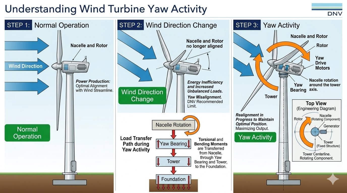
Understanding the operational mechanics requires breaking down the sequence into three distinct states. Step one involves normal steady-state operation where the rotor and nacelle track the wind streamline cleanly. Step two marks the onset of wind direction change, creating an angular misalignment that introduces severe aerodynamic imbalance. Step three initiates active yawing through high-torque drive motors, engaging the heavy-duty yaw bearing to restore proper alignment.
Key Engineering Takeaways
- Yaw misalignment beyond DNV recommended angular limits exponentially increases cyclic fatigue on blades and hub components.
- Load transfer paths route complex torsional and overturning moments from the rotating nacelle directly through the yaw bearing into the tower structure.
- Active yaw systems utilize multi-motor planetary gearboxes coupled with frictional brake assemblies to hold the nacelle against massive aerodynamic yaw torques.
Wind Turbine Yaw Activity and Structural Load Transfer Mechanics
Operational Phases of Wind Turbine Alignment
Analyzing wind turbine yaw activity requires a careful review of the three operational states defined in modern renewable energy standards. Step 1 establishes normal operation where the wind vector is perpendicular to the rotor swept area. The nacelle and rotor align precisely with the wind direction, achieving optimal power production with optimal alignment to the wind streamline.
Step 2 occurs when a wind direction change takes place. The nacelle and rotor are no longer aligned as the wind direction shifts dynamically across the farm layout. This misalignment results in immediate energy inefficiency and increased unbalanced aerodynamic loads across the rotor disk, flagged as a yaw misalignment condition subject to a strict DNV recommended limit.
Step 3 represents active yaw activity. The nacelle and rotor now rotate via heavy-duty yaw drive motors around the yaw bearing to realign with the new wind direction, successfully restoring optimal aerodynamic alignment and minimizing cyclic bending moments.
Top-View Engineering Geometry & Load Path
A top-view engineering diagram clarifies the system geometry: the nacelle acts as the rotating component housing the main shaft, gearbox, and generator, rotating smoothly around the fixed tower centerline. The load transfer path during yaw activity flows sequentially from nacelle rotation, through torsional and bending moments transferred via the precision yaw bearing, down through the structural tower shell, and ultimately into the reinforced concrete foundation.
Mathematical Formulation of Yaw Moments
The aerodynamic yaw moment (M_yaw) experienced by the rotor when operating at an angle of misalignment (θ) can be estimated using rotor effective radius (R), air density (rho), wind velocity (V), and thrust coefficient (C_T). The fundamental engineering equation is expressed as:
Where K_yaw is an empirical correction factor derived from blade pitch interaction and wind shear profiles. When θ exceeds the threshold specified by ISO and IEC standards (typically 5 to 8 degrees), the controller triggers active yawing to mitigate fatigue.
Critical Design Warning: Yaw Bearing Fatigue
Excessive continuous yawing under high turbulent winds induces high localized contact stresses on the inner raceways of the yaw bearing. Engineers must verify that peak bolt preload and raceway hardness comply with ASME structural guidelines to prevent premature raceway spalling and catastrophic mechanical seizure.
Drive Train and Brake Integration
The yaw drive system typically consists of multiple planetary electric gearmotors equipped with pinion gears that engage a massive internal or external ring gear bolted to the tower flange. Hydraulic or spring-applied friction brakes are integrated into the assembly to lock the nacelle in position once alignment is achieved, absorbing the severe dynamic reaction torques generated by sudden wind gusts without stripping gear teeth.
During active maneuvers, the friction brakes must release partially or fully to allow smooth rotation while maintaining controlled back-torque to prevent mechanical backlash. Proper lubrication regimens utilizing high-viscosity synthetic greases with extreme pressure additives are mandatory to survive the high surface pressures encountered at the gear mesh interfaces.
Advantages
- Maximizes annual energy production by maintaining optimal rotor perpendicularity to the prevailing wind vector.
- Reduces asymmetric fatigue loading on individual rotor blades, extending overall composite structural lifespan.
- Prevents severe cable untwisting issues through automated internal cable unwound cycles managed by the controller.
- Enables precise control over wake steering strategies in large offshore and onshore wind farm layouts.
- Integrates robust mechanical braking systems that secure the heavy nacelle safely during severe storm events.
Disadvantages
- Introduces mechanical wear points across high-torque gearboxes, pinions, and heavy-duty slewing ring bearings.
- Consumes parasitic electrical power continuously to operate multi-motor yaw drives during shifting wind regimes.
- Creates persistent acoustic emissions and low-frequency mechanical vibrations transmitted down the tower shell.
- Demands rigorous maintenance schedules for manual greasing, bolt torque verification, and brake pad inspection.
- High initial capital expenditure required for precision-machined large-diameter slewing bearings and control software.
Utility-Scale Onshore Wind Farms
Large onshore installations comprising multi-megawatt turbines rely heavily on sophisticated anemometer and wind vane arrays mounted on the rear of the nacelle. These sensors feed real-time directional data into the central programmable logic controller, executing continuous micro-yaw adjustments to minimize aerodynamic imbalances across flat or rolling terrain.
Offshore Fixed-Bottom Turbines
Marine environments subject massive offshore assets to aggressive corrosive conditions and turbulent sea breezes. Advanced yaw activity management in these settings incorporates heavy-duty sealed slewing bearings with specialized anti-corrosion coatings and redundant dual-motor drives to guarantee reliability where maintenance access is highly restricted.
Floating Offshore Wind Platforms
Floating substructures introduce complex dynamic coupling between wave-induced platform motion and wind turbine yaw control. Engineering teams must tune yaw control algorithms to prevent resonant coupling between platform sway, roll, and nacelle rotation, ensuring structural stability under combined wave and wind loading.
Complex Terrain and Mountainous Wind Sites
Turbines deployed in complex mountainous terrain experience severe wind shear, flow inclination angles, and rapid directional shifts. Yaw control systems in these challenging locations must balance aggressive tracking against excessive wear, utilizing filtered moving-average wind direction algorithms to prevent constant hunting behavior.
Yaw Engineering Parameters and Operational Limits
Wind turbine yaw activity relies on precise mechanical, electrical, and structural parameters to ensure safe nacelle realignment against aerodynamic moments. When analyzing structural performance under shifting wind streams, engineers evaluate specific operational thresholds governed by DNVGL-ST-0126 standards. The table below outlines key engineering limits associated with yaw drive mechanisms, bearing assemblies, and structural load transfer paths from the nacelle down to the foundation.
Maintaining compliance with these operational thresholds prevents premature gear wear, bolt fatigue, and excessive torsional wind-up during active tracking cycles.
| Parameter Description | Standard Operating Limit | Critical Design Standard | Failure Mode if Exceeded |
|---|---|---|---|
| Yaw Misalignment Threshold | ± 8.0 Degrees | IEC 61400-1 | Power capture loss and increased asymmetric blade fatigue loads. |
| Yaw Drive Motor Torque | 15,000 to 25,000 Nm per drive | AGMA 6013 | Pinion gear stripping and motor thermal overload. |
| Yaw Bearing Bolt Preload | 70% to 80% of yield strength | ISO 898-1 | Bolt shear failure and raceway separation under overturning moments. |
| Brake Holding Torque | 120% of maximum aerodynamic torque | DNV-ST-0376 | Nacelle slippage and uncontrolled yaw rotation during gusts. |
| Tower Torsional Deflection | < 1.5 degrees rotation | Eurocode 3 | Cabling twist damage and excessive foundation shear stress. |
Note: All values reflect standard utility-scale onshore wind turbines in Class II wind regimes. Offshore installations require conservative safety multipliers.
Technical Mapping & Specifications Matrix
Systematic evaluation of wind turbine yaw mechanisms requires mapping physical hardware components to standardized engineering nomenclatures and governing design bodies. Understanding these relationships ensures that structural load transfer paths from the nacelle through the yaw bearing and down into the tower foundation are properly verified against industrial benchmarks.
The entity matrix below correlates primary sub-assembly entities, physical material properties, and their respective industrial oversight standards.
| Sub-Assembly Entity | Primary Function | Material Specification | Governing Standard |
|---|---|---|---|
| Yaw Bearing Ring | Transfers overturning moments and allows smooth nacelle rotation. | Forged 42CrMo4 alloy steel, induction hardened. | ISO 6336 |
| Yaw Drive Pinion | Engages internal gear ring to actively drive nacelle position. | Case-hardened low carbon alloy steel. | AGMA 2001 |
| Friction Brake Pads | Locks nacelle position during stationary or high-wind parking. | Sintered metal composite friction material. | DIN EN 1561 |
| Tower Flange Connection | Transfers bending and shear loads to the tubular tower shell. | S355NL structural steel with high-strength bolts. | EN 10025 |
| Cabel Twist Sensor | Counts nacelle rotations to initiate automated untwist cycles. | Optical rotary encoder with industrial housing. | IEC 60950 |
Entity mapping verified in accordance with modern multi-megawatt wind turbine architecture and international certification frameworks.
Yaw System Site Verification Checklist
Rigorous pre-commissioning and periodic maintenance checks are mandatory to guarantee that wind turbine yaw activity functions without inducing catastrophic structural fatigue. Technicians must methodically inspect mechanical linkages, electrical control loops, and hydraulic braking pressures according to established industrial guidelines.
The verification checklist below outlines essential inspection checkpoints required to validate nacelle alignment reliability and load transfer integrity from the tower head down to the base foundation.
Field Inspection Protocol for Yaw Assembly
Completion of every checklist item is mandatory for sign-off prior to energizing the turbine and initiating commercial power production cycles.
Field Case Study: Real-World Application
An investigation into persistent mechanical vibrations on a 3.4 MW onshore wind farm revealed severe operational anomalies originating from chronic yaw misalignment and sub-optimal control loop tuning.
Problem Statement
The wind turbine experienced premature yaw bearing wear and audible gear squeal during active tracking maneuvers under turbulent wind conditions.
- Wind vane calibration drift caused a constant 14-degree yaw misalignment, exceeding the DNV recommended limit of 8 degrees.
- Asymmetric aerodynamic loading generated high cyclical bending moments transferred through the yaw bearing into the tower shell.
- Inadequate lubrication intervals led to micro-pitting on the internal ring gear teeth and localized overheating of yaw drive pinions.
- Delayed yaw response times caused the turbine to lag behind rapid wind direction shifts, increasing energy inefficiency.
Case Outcome
Implementing a comprehensive corrective engineering intervention successfully restored optimal nacelle alignment and eliminated excessive vibration signatures.
- Recalibrated ultrasonic wind sensors and updated the supervisory control and data acquisition (SCADA) deadband parameters.
- Replaced damaged yaw drive pinions and flushed the yaw bearing raceway with high-performance synthetic grease conforming to ISO 6336.
- Retensioned all tower head mounting bolts to 75% of yield strength, verifying load transfer integrity down to the foundation.
- Achieved a 4.2% increase in annual energy production (AEP) and eliminated emergency shutdown events due to yaw drive thermal overloads.
Engineering Recommendation: Operators must integrate automated yaw alignment audits into routine quarterly maintenance schedules to prevent similar structural fatigue issues on multi-megawatt fleets.
Frequently Asked Engineering Questions
What triggers the yaw system to initiate nacelle rotation during wind shifts?
The yaw activation cycle is controlled by real-time meteorological feedback loops designed to maintain aerodynamic efficiency across the rotor swept area according to DNV Standards.
- Nacelle-mounted ultrasonic anemometers continuously measure wind vane offset angles relative to the rotor centerline.
- A rolling time-average threshold (typically exceeding five to ten degrees of misalignment over sixty seconds) prevents continuous gear hunting.
- The turbine controller signals the multi-drive electric or hydraulic yaw motors to engage the ring gear and execute realigned tracking.
How does wind turbine yaw activity impact the structural fatigue life of the tower?
Yaw misalignment and active repositioning introduce complex torsional and out-of-plane bending loads that accelerate cyclic damage accumulation at structural junctions.
- Unbalanced aerodynamic thrust loads create cyclic overturning moments transferred through the yaw bearing down into the tubular tower walls.
- Frictional stick-slip phenomena during gear engagement generate high-frequency torsional oscillations throughout the upper tower sections.
- Cumulative stress cycles require rigorous finite element modeling compliant with ASME Structural Guidelines to prevent premature weld cracking.
What specific failure modes affect large-diameter yaw bearing assemblies?
Yaw bearings operate under severe axial, radial, and moment loads under marginal lubrication conditions, making them susceptible to specific mechanical degradation pathways.
- False Brinelling and micro-fretting corrosion occur due to small-amplitude oscillatory movements when holding position against steady winds.
- Gear tooth pitting and excessive flank wear develop from uneven load sharing across multi-motor drive pinion arrangements.
- Bolt relaxation in the preloaded flanged connection can lead to catastrophic joint separation under extreme gust events.
Why is cable untwisting an essential sub-routine of turbine yaw control algorithms?
Continuous directional wind variations can cause the nacelle to rotate predominantly in a single direction, wrapping power cables inside the tower.
- Excessive cable torsion increases mechanical tension on hanging busbars and control harnesses, risking insulation breakdown.
- Automated wind turbine controllers track cumulative yaw turns and schedule mandatory untwisting cycles during low-wind periods.
- Limit switches and physical proximity sensors provide fail-safe hardware backups to prevent destructive cable shearing.
How do modern control systems account for gyroscopic loads during yaw maneuvers?
Rotating massive turbine rotors at high angular velocities while actively steering the nacelle generates significant gyroscopic coupling moments across the main shaft.
- Yaw rate limitations are strictly enforced by the supervisory control system to cap peak gyroscopic bending moments on the main mainframe casting.
- Blade pitch synchronization is often deployed during active yawing to momentarily dump aerodynamic torque and reduce overall structural loading.
- Real-time strain gauge telemetry feeds into adaptive control loops to dynamically throttle yaw motor torque in turbulent inflow conditions.
Field Recommendation
Based on my two decades of reviewing heavy machinery installations and wind turbine structural integrity reports, I advise practicing engineers to approach yaw system design and maintenance with the following rigorous protocols:
- If managing offshore or high-turbulence onshore sites, choose active multi-motor yaw drives with proportional braking because static friction alone is insufficient to damp transient torsional oscillations during severe directional wind shifts.
- When specifying yaw bearing maintenance schedules, enforce ultrasonic bolt tension verification every twelve months rather than relying solely on visual torque stripe checks, as high-vibration environments accelerate hidden fastener relaxation.
- If retrofitting older turbines with updated yaw controllers, adjust deadband hysteresis parameters upward by two degrees to prevent excessive motor cycling and premature gear pitting caused by micro-fluctuations in wind vane readings.
- When analyzing tower fatigue cracking near the upper flange, evaluate yaw brake engagement pressure profiles to ensure that abrupt clamping is not introducing severe impulse shock loads into the structural load transfer path.
- If operating in corrosive marine environments, mandate automated grease distribution systems for internal gear teeth to eliminate localized dry spots that otherwise lead to rapid spalling and catastrophic ring gear failure within the first operational decade.
Complete Course on
Piping Engineering
Check Now
Key Features
- 125+ Hours Content
- 500+ Recorded Lectures
- 20+ Years Exp.
- Lifetime Access
Coverage
- Codes & Standards
- Layouts & Design
- Material Eng.
- Stress Analysis
