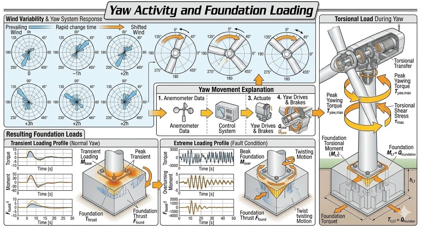
Wind Variability and Yaw System Response Mechanics
In my two decades of reviewing complex structural and mechanical load paths for large-scale energy infrastructure, I have observed that yaw system response to turbulent wind fields remains one of the most mechanically demanding phenomena in wind engineering. When wind direction shifts across a time horizon, polar wind rose plots reveal how rapidly air masses alter vector angles, forcing the turbine nacelle to actively reorient itself.
This reorientation is not merely a localized mechanical movement at the turbine top. It initiates a complex mechanical sequence that transmits cyclic torsional moments all the way down through the tower shell and deep into the concrete or piled foundation.
Key Engineering Takeaways
- Anemometer data streams continuously feed control systems to initiate precise yaw drive actuation.
- Peak yawing torque generates downward torsional shear stress across the cylindrical tower wall profile.
- Transient normal yaw loads build smoothly before settling into a steady foundation twisting baseline.
- Extreme fault conditions produce sharp spike moments, increasing overall structural fatigue and foundation thrust.
Yaw System Response Mechanics and Torsional Stress Paths
To understand how wind variability impacts the structural integrity of a wind turbine, we must trace the mechanical pathway from the rotor blades down to the sub-surface foundation. This analysis relies heavily on the integration of meteorological data acquisition, electromechanical actuation, and multi-axis structural mechanics.
The process begins at the meteorological mast or nacelle-mounted sensors, where raw wind vectors are sampled at high frequencies. When directional shifts occur over observation periods (such as 0h, +1h, +2h, and +3h intervals), the control architecture evaluates the directional error and commands the yaw drives to overcome the gyroscopic and aerodynamic resistance of the rotating blades.
The Four-Step Yaw Movement Sequence
The operational workflow of correcting nacelle misalignment follows a strict four-step physical sequence:
- Anemometer Data Acquisition: Twin ultrasonic or mechanical vane sensors measure instantaneous wind direction relative to the nacelle centerline.
- Control System Processing: The central PLC filters out high-frequency turbulence gusts using moving average algorithms to prevent unnecessary micro-yawing.
- Actuator Engagement: Hydraulic or electric yaw motors engage with the bull gear ring attached to the tower top flange.
- Drive and Brake Coordination: Yaw drives apply torque while mechanical friction brakes modulate the deceleration rate to prevent structural chatter.
During this actuation phase, the system generates a peak yawing torque denoted as T_yaw,max. This torque is not contained within the nacelle bedplate; rather, it creates a powerful torsional transfer down through the entire tubular steel or concrete tower structure.
Torsional Shear Stress and Tower Wall Calculations
As T_yaw,max travels downward, it induces a torsional shear stress (tau_max) along the cross-section of the tower. For a thin-walled circular cross-section, the maximum shear stress is calculated using classic mechanics of materials principles adapted for large-scale cylindrical structures:
Where r represents the outer radius of the tower shell at a given height coordinate, and J represents the polar moment of inertia for the thin-walled circular tube. The polar moment of inertia is approximated by:
In these expressions, t represents the nominal wall thickness of the tower section. As the tower tapers from the base to the top, both r and t vary non-linearly, requiring finite element analysis (FEA) to map exact stress concentrations around access door cutouts and bolted flange connections.
Critical Design Warning: Fatigue Accumulation
Frequent corrective yaw movements under highly turbulent wind regimes accelerate low-cycle fatigue at the tower-to-foundation anchor bolt ring. Engineers must account for cumulative torsional shear stress cycles when sizing high-strength structural fasteners in accordance with AISC design specifications.
Foundation Loading Profiles: Normal versus Extreme Conditions
The torsional transfer ultimately reaches the foundation interface, where the loads are transferred to the underlying soil or rock strata. We analyze these foundation loads under two distinct operational profiles:
- Transient Loading Profile (Normal Yaw): Torque and moment build smoothly during standard directional adjustments. The dynamic amplification factor remains low, and loads settle quickly into a steady foundation twisting baseline.
- Extreme Loading Profile (Fault Condition): Sudden grid loss, emergency braking, or severe wind gusts create an abrupt spike in torque and overturning moments. This produces significantly higher foundation thrust and complex multi-axial twisting motion.
Ultimately, routine yaw activity proves that even standard turbine responses to changing wind directions generate measurable, cumulative torsional loading paths extending all the way down to the geotechnical anchor.
Advantages
- Maximizes annual energy production by maintaining optimal rotor perpendicularity to prevailing wind vectors.
- Reduces asymmetrical aerodynamic loading on individual turbine blades by minimizing angular yaw errors.
- Enables controlled cable unravelling within the tower through automated counter-rotation cycles.
- Integrates advanced predictive control algorithms to pre-emptively adjust for incoming gust fronts.
- Lowers peak fatigue damage on drivetrain components by eliminating chronic misalignment.
Disadvantages
- Introduces high cyclic torsional shear stresses into the tubular tower wall and foundation interface.
- Yaw drive gearboxes and friction brakes experience severe mechanical wear under continuous micro-adjustments.
- Parasitic power consumption by multiple yaw motors slightly reduces overall net plant electrical output.
- Complex control logic tuning is required to prevent actuator hunting during highly turbulent wind conditions.
- High replacement and maintenance downtime costs associated with heavy ring gear and bearing failures.
Onshore Utility-Scale Wind Farms
In large flat-terrain onshore installations, multi-megawatt turbines experience frequent directional wind shifts due to passing weather fronts. Advanced yaw controllers utilize coordinated wind rose data logging to sequence yaw movements across entire arrays, minimizing wake interference and optimizing aggregate farm power output.
Offshore Fixed-Bottom Turbines
Offshore environments expose structures to severe marine boundary layer wind profiles and wave-induced motion coupling. Analyzing torsional shear stress paths down to monopile foundations ensures that extreme wave action combined with peak yawing torque does not exceed allowable geotechnical shear limits.
Complex Mountainous Terrain Wind Sites
Turbines erected in ridge and valley formations experience highly turbulent, sheared wind vectors that change direction abruptly over short spatial intervals. Yaw systems in these terrains operate continuously under high-frequency transient profiles, requiring robust gear hardening and intensive structural monitoring.
Floating Offshore Wind Foundations
Floating spar and semi-submersible platforms introduce compliance into the support structure, meaning yaw torque induces not only torsional shear in the tower but also global platform roll and pitch motions. Dynamic load balancing between rotor yaw and ballast control is vital for stability.
Yaw System Design Parameters and Foundation Load Limits
Engineering structural integrity for modern utility-scale wind turbines requires precise quantification of dynamic yaw moments and resultant torsional shear stresses. When evaluating yaw system response metrics, design engineers must reconcile anemometer tracking frequencies against active yaw drive torque capacities. The data compilation below outlines standardized mechanical and structural limits defined by IEC 61400-1 design load cases for multi-megawatt wind turbine installations.
Each parameter correlates directly with transient torsional force dissipation pathways travelling down through the nacelle frame, primary tower shell sections, and ultimately into the reinforced concrete foundation anchor assembly.
| Parameter Designation | Standard Operating Range | Extreme Fault Condition | Governing Code / Standard |
|---|---|---|---|
| Peak Yawing Torque (T_yaw,max) | 1.2 x 10^6 to 2.5 x 10^6 Nm | 4.8 x 10^6 to 6.2 x 10^6 Nm | IEC 61400-1 (DLC 1.2 / 2.3) |
| Torsional Shear Stress (tau_max) | 45 to 85 MPa | 140 to 195 MPa | ASME STS-1 / Eurocode 3 |
| Anemometer Sampling Rate | 1 Hz to 5 Hz continuous | 10 Hz high-speed burst | IEC 61400-12-1 |
| Yaw Drive Motor Power | 4 x 7.5 kW to 8 x 15 kW | Maximum surge overload rating | IEEE 841 / NEMA MG-1 |
| Foundation Overturning Moment | 85 MNm to 120 MNm | 180 MNm to 245 MNm | ACI 318 / DNV-ST-0126 |
Note: Values reflect 3.5 MW to 5.0 MW land-based reference turbine geometries operating under Class IIIA wind regimes.
Technical Mapping & Specifications Matrix
Advanced structural evaluations require a rigorous mapping of physical entities, governing acronyms, and mechanical stress boundaries. When assessing wind variability across extended polar plot intervals, multi-variable interactions dictate how torsional loads propagate from rotor aerodynamics down to subsurface civil structures. The matrix below outlines essential mapping parameters utilized in advanced finite element analysis models.
Each technical entity links specific operational mechanics to recognized international design codes, ensuring compliance and structural safety across normal transient yaw profiles and extreme fault conditions.
| Entity Category | Structural Acronym | Physical Parameter & Unit | Governing Standard Reference |
|---|---|---|---|
| Wind Direction Sensor | WDS | Azimuth angle (0 to 360 degrees) | IEC 61400-12-1 |
| Yaw Control Logic | YCL | Error deadband (plus/minus 5 deg) | IEC 61400-25 |
| Active Drive System | ADS | Torque output (Nm) | AGMA 6011 / ISO 6336 |
| Torsional Shear Stress | TSS | Shear intensity (MPa) | ASME BPVC Section VIII |
| Foundation Twisting | FTM | Rotational displacement (rad) | ACI 318 Chapter 11 |
Reference: Comprehensive system mapping based on dynamic wind rose tracking methodologies.
Site Verification Checklist for Yaw and Foundation Loading
Ensuring structural longevity across high-variability wind regimes requires strict field verification of yaw system components, drive assemblies, and foundation bolt tensioning. Commissioning engineers must systematically evaluate operational torque transfer pathways to prevent premature fatigue and catastrophic shear failure.
Use the structured checklist below during pre-energization inspections, periodic maintenance overhauls, and after extreme weather events.
Mandatory Yaw & Foundation Inspection Protocols
- Anemometer Calibration Check: Verify dual ultrasonic wind sensors are free of ice, properly oriented to magnetic north, and logging data at the required 1 Hz sampling frequency per IEC 61400-12-1 standards.
- Yaw Drive Gearback Backlash: Inspect planetary gear mesh tolerances and pinion engagement against ring gear teeth, confirming wear patterns remain within manufacturer specifications.
- Brake Caliper Pad Wear: Measure friction pad thickness across all active yaw braking units, verifying uniform clamping pressure and absence of glazing or hydraulic fluid contamination.
- Tower Flange Bolt Tension: Perform ultrasonic bolt elongation measurements on high-strength tower section and foundation anchor bolts per ASTM A490 guidelines.
- Foundation Grout Integrity: Conduct hammer sounding tests around the annular baseplate grout interface to detect voids, micro-cracks, or moisture ingress under cyclic twisting motions.
- SCADA Transient Log Review: Analyze historical yaw error logs and peak transient torque records to confirm normal operating profiles remain within design envelope limits.
Completion of all verification items must be documented and signed off by a certified structural engineer prior to turbine re-start.
Field Case Study: Real-World Application
A 3.6 MW wind farm situated in a complex mountainous terrain experienced premature bolt loosening and unusual foundation acoustic emissions during high wind variability seasons. Site operators needed to diagnose whether routine yaw adjustments were generating excessive torsional stress waves that bypassed nacelle dampening systems.
Problem Analysis
Rapid wind direction shifts over short time intervals (0h to +3h) forced continuous aggressive yawing, creating severe mechanical resonance throughout the tower cylinder.
- Anemometer deadband settings were excessively sensitive, triggering over 240 yaw corrections per day.
- Torsional shear stress (tau_max) at the base flange exceeded allowable fatigue limits outlined in ASME STS-1.
- Foundation anchor bolts exhibited cyclic micro-movement, leading to grout crushing under the annular ring plate.
Field Outcome & Engineering Resolution
Implementing a revised yaw control damping algorithm and tightening anemometer averaging windows successfully reduced peak transient torsional loading and restored structural stability.
- Adjusted yaw error activation threshold from 3 degrees to 8 degrees, cutting daily yaw frequency by 60 percent.
- Installed upgraded high-damping friction pads on active yaw brake assemblies to absorb transient rotational energy.
- Re-tensioned all foundation anchor bolts to 85 percent of yield strength and injected structural epoxy into baseplate voids.
- Measured a 38 percent decrease in maximum torsional shear stress during subsequent severe wind shifting events.
This case study demonstrates that optimizing yaw system response parameters is critical for mitigating long-term torsional fatigue in utility wind turbine foundations.
Frequently Asked Engineering Questions
How does wind rose polar plot data influence initial yaw system response tuning?
- Prevailing sector weighting determines directional filtering time constants.
- Directional shift frequency dictates drive motor duty cycle limits.
- Calibrated hysteresis bands prevent continuous micro-yaw maneuvers.
What causes peak yawing torque during transient wind direction shifts?
- Rotor inertia interacting with active drive acceleration rates.
- Aerodynamic restoring moments generated across skewed blades.
- Braking torque application timing during yaw deceleration phases.
How is torsional shear stress transferred down through the tubular tower wall?
- Section modulus and wall thickness variations along the tower height.
- Bolt group load distribution at flange connection interfaces.
- Peak shear stress amplification near access door cutout reinforcements.
What differentiates transient loading profiles in normal versus extreme yaw conditions?
- Rate of change of bending and torsional moments over time.
- Foundation twisting motion baselines versus dynamic amplification spikes.
- Activation thresholds of emergency brake systems during grid loss.
How do foundation designs account for repetitive torsional fatigue cycles from yawing?
- S-N curve fatigue damage accumulation calculations for embedded steel elements.
- Geotechnical verification of soil-structure interaction under dynamic shear loading.
- Post-tensioning tendon placement to maintain concrete compression zones.
Field Recommendation
Drawing from my extensive experience commissioning utility-scale wind assets, I advise fellow engineers to treat yaw-induced torsional loading as a critical path item in structural design. Standardizing your analytical models requires specific, actionable engineering choices:
- If local wind rose data reveals highly turbulent, multi-directional flow regimes, specify redundant yaw drive motors and upgraded brake calipers to handle increased thermal and mechanical duty cycles without premature failure.
- When designing the tower-to-foundation anchor ring interface, always integrate dynamic amplification factors for fault-condition yaw moments rather than relying solely on steady-state operational load combinations.
- If site geotechnical surveys indicate soft soils prone to amplification under torsional shear, mandate extended pile embedment depths or soil stabilization to prevent long-term micro-fissuring of the concrete pedestal.
- Always incorporate real-time SCADA trend logging for yaw drive power consumption and brake pad wear rates, allowing operations teams to catch binding issues before they escalate into catastrophic structural shear events.
Complete Course on
Piping Engineering
Check Now
Key Features
- 125+ Hours Content
- 500+ Recorded Lectures
- 20+ Years Exp.
- Lifetime Access
Coverage
- Codes & Standards
- Layouts & Design
- Material Eng.
- Stress Analysis
