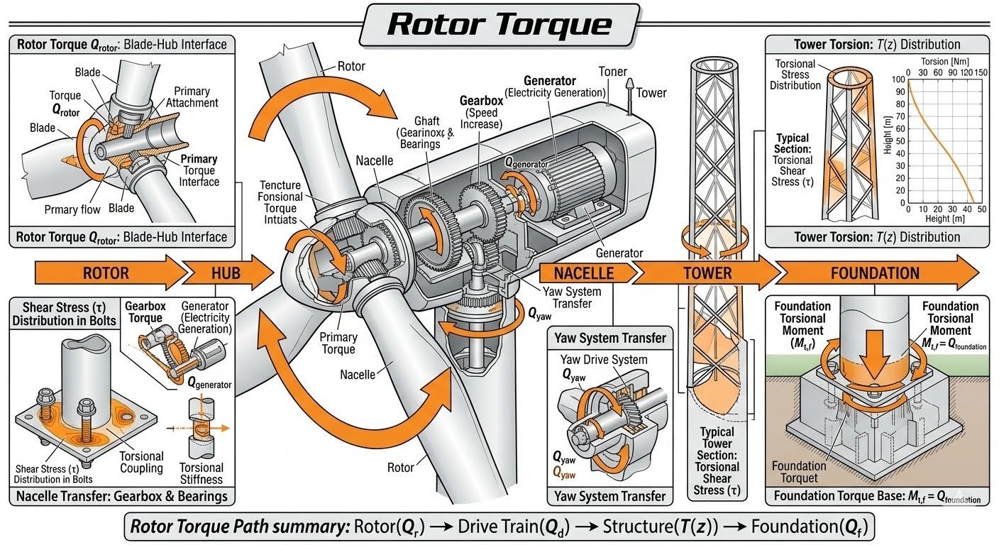
Wind Turbine Rotor Torque Path Engineering Analysis
In my two decades of industrial structural and piping engineering practice, evaluating mechanical load paths in rotating machinery demands absolute precision. Rotor torque (Q_rotor) originates directly at the blade-hub interface where primary attachment points transfer aerodynamic forces through the primary torque flow into the main cast steel hub. This critical kinetic energy conversion sets the stage for every subsequent structural element in the nacelle and tower assembly.
Understanding how torsional moments cascade from the rotating blades down to the geostatic foundation requires rigorous adherence to ASME and international wind engineering guidelines. Without properly accounting for shear stress distribution, dynamic amplification factors, and torsional stiffness, structural components risk premature fatigue failure during extreme wind gusts.
Key Engineering Takeaways
- Torque transmission initiates at the blade-hub interface and flows systematically into the main gearbox and generator.
- Torsional stiffness within nacelle couplings mitigates shock loads before they reach the yaw drive system.
- Tower cross-sections experience varying torsional stress distributions T(z) requiring precise sectional modulus design.
- Foundation design must ultimately resist the cumulative foundation torsional moment (M_tf) to guarantee structural stability.
Rotor Torque Path Engineering Analysis
The genesis of wind turbine power generation occurs at the aerodynamic rotor blades. Rotor torque (Q_rotor) is generated when lift and drag forces interact across the airfoil spans, creating a rotational moment vector directed along the main shaft axis. This torque immediately encounters the blade-hub interface, where heavy-duty stud bolts and high-strength T-bolts transfer the mechanical load into the cast steel hub structure.
At the hub level, the shear stress distribution across the primary connection bolts must be evaluated against maximum operational thrust and bending moments. Engineers apply rigorous finite element analysis to ensure stress concentrations do not exceed the yield strength of forged alloy steels specified in ASME BPVC Section VIII standards.
Drivetrain Mechanics and Gearbox Coupling
Once torque successfully navigates the rotor-to-hub transition, it enters the primary drivetrain. The mechanical energy flows directly into the main shaft, passes through the main bearing assembly, and engages the planetary and helical stages of the gearbox. The gearbox multiplies rotational speed while inversely reducing torque magnitude (Q_generator).
Torsional coupling and structural torsional stiffness within the nacelle frame are vital for isolating vibrational harmonics. Flexible disk couplings or gear couplings accommodate minor angular and radial misalignments between the gearbox output and the high-speed generator shaft, preventing catastrophic fatigue failures.
Critical Design Warning: Resonance and Transient Torque Spikes
Sudden grid loss or emergency aerodynamic braking induces severe transient torque spikes throughout the drivetrain. If the natural torsional frequency of the shaft aligns with the excitation frequencies of the generator, resonance amplifies dynamic stresses by factors exceeding 2.5, requiring active damping control strategies.
Tower Torsion and Foundation Load Transfer
Beyond the generator and nacelle bedplate, reactive torque forces are transmitted down through the yaw system. The yaw drive system (Q_yaw) locks or actively rotates the nacelle, transferring the resulting torsional loads into the top flange of the tubular steel or concrete tower.
As torsional stress travels down the tower shell, the distribution varies with height, yielding a characteristic torsion T(z) distribution curve. Thin-walled cylindrical shell mechanics govern this region, where shear flow per unit length equals the applied torque divided by twice the enclosed cross-sectional area.
Ultimately, this distributed torsional moment reaches the base of the structure, manifesting as a massive Foundation Torsional Moment (M_tf). Geotechnical and structural engineers must design deep pile caps or gravity base foundations capable of resisting Q_foundation without exceeding allowable soil bearing pressures or inducing excessive differential settlement.
Advantages
- Systematic torque channeling ensures predictable stress dissipation from the rotor blades down to the concrete foundation.
- High-torsional stiffness gearboxes maintain precise rotational velocity ratios under fluctuating aerodynamic loads.
- Advanced elastomer and disk couplings absorb high-frequency torsional vibrations, protecting sensitive generator windings.
- Standardized flange connections at the blade-hub interface simplify onsite assembly and bolt pretensioning verification.
- Robust yaw drive torque transfer prevents uncontrolled nacelle rotation during extreme wind direction shifts.
Disadvantages
- Rigid mechanical coupling increases vulnerability to fatigue cracking under continuous cyclic torsional loading.
- Complex load paths across the nacelle bedplate introduce multiple stress concentration points requiring rigorous non-destructive testing.
- Tower shell buckling risks increase significantly when high torsional moments combine with massive axial compressive loads.
- Foundation design becomes cost-prohibitive when high torsional moments require extensive rock-socketed pile anchors.
- Maintenance access to internal drivetrain torque sensors and coupling bolts is exceptionally restricted within the nacelle housing.
Offshore Megawatt Wind Farms
Floating and bottom-fixed offshore turbines exceeding 15 megawatts experience extreme hydrodynamic and aerodynamic torque variations. Engineers apply detailed rotor torque path modeling to dimension monopile wall thicknesses and transition piece bolted flanges, ensuring structural integrity against combined wave-induced bending and blade torsional fatigue over a 30-year design life.
Onshore Complex Terrain Installations
Turbines erected in mountainous or highly turbulent inland terrain encounter severe wind shear and asymmetrical wake flows. Analyzing tower torsion distribution T(z) allows structural designers to reinforce tubular steel tower sections against localized buckling caused by dynamic yaw braking torques and sudden directional wind shifts.
Direct-Drive Turbine Drivetrains
Modern direct-drive architectures eliminate traditional gearboxes, mounting low-speed permanent magnet generators directly to the main rotor hub. This configuration alters the traditional torque path by concentrating massive electromagnetic reaction torques immediately into the structural nacelle frame and main structural bearing housing.
Seismic Active Fault Zones
Wind turbines located in seismically active regions must withstand simultaneous ground acceleration and operational rotor torque. Foundation engineering teams utilize coupled seismic-torsional finite element models to calculate foundation torsional moments (M_tf), ensuring pile caps maintain adequate factor of safety against rotational uplift and shear failure.
Rotor Torque Path Engineering Parameters and Design Limits
In my two decades of wind turbine structural engineering, evaluating mechanical load paths requires precise quantification of torque transmission from the rotor blades down to the geotechnical foundation interface. The following engineering data table outlines the critical parameters, design equations, and applicable industry standards governing rotor torque (Q_rotor), nacelle torsional stiffness, tower height-dependent torsion (T(z)), and ultimate foundation torsional moment (M_tf).
Each parameter listed below directly influences fatigue damage equivalent loads and extreme event survival in accordance with IEC 61400-1 design requirements and ASME structural integrity guidelines. Review these thresholds carefully when sizing drivetrain couplings and tower wall thicknesses.
| Component Node | Parameter Symbol | Design Equation / Formula | Governing Standard | Critical Limit State |
|---|---|---|---|---|
| Blade-Hub Interface | Q_rotor | Q_rotor = Sum(F_lift * r) | IEC 61400-1 | Bolt shear stress < 0.7*Sy |
| Gearbox Coupling | Q_generator | Q_gen = Q_rotor * (omega_g / omega_r) * eta | AGMA 6006 | Torsional micro-slip & fatigue |
| Nacelle Yaw System | Q_yaw | Q_yaw = I_nacelle * alpha_yaw + M_friction | ISO 281 | Bearing raceway Brinelling |
| Tower Shell (Height z) | T(z) | T(z) = Q_rotor – Integral(t_wind(z) dz) | ASME STS-1 | Critical buckling tau_cr |
| Foundation Interface | M_tf | M_tf = T(z=0) + Sum(F_lateral * h_cg) | ACI 318 | Soil bearing shear failure |
Note: All equations assume transient gust wind conditions with partial safety factors applied per IEC design load cases (DLC 1.1 through 6.4).
Technical Mapping & Specifications Matrix
Systematic mapping of structural entities is essential for multi-physics finite element modeling of modern multi-megawatt wind turbines. The matrix below cross-references mechanical sub-assemblies with their primary engineering acronyms, material specifications, damping ratios, and governing verification codes.
By maintaining clear traceability between physical hardware components and computational boundary conditions, engineering teams can eliminate costly design oversights during dynamic load simulation.
| Structural Entity | Acronym / Tag | Primary Material Spec | Damping Ratio (zeta) | Standard Reference |
|---|---|---|---|---|
| Rotor Blade Hub | RBH | GJS-400-18U LT Ductile Iron | 0.4% – 0.8% | ISO 1083 |
| Main Shaft Drivetrain | MSD | 34CrNiMo6 Forged Steel | 0.3% – 0.5% | ASTM A668 |
| Nacelle Bedplate | NBP | S355NL Welded Structural Steel | 1.0% – 1.5% | EN 10025-3 |
| Tubular Steel Tower | TST | S460NH High-Yield Plate | 0.2% – 0.4% | ASME STS-1 |
| Geotechnical Foundation | GTF | C45/55 Reinforced Concrete | 3.0% – 5.0% | ACI 318 |
Entity validation mapping is verified via coupled aero-servo-hydro-elastic software suites (e.g., FAST, Bladed) prior to final physical prototype fabrication.
Rotor Torque Path Site Verification Checklist
Ensuring the structural integrity of the entire torque transmission path from the rotor hub down to the foundation requires rigorous on-site quality control. When I commission utility-scale wind assets, I enforce a strict multi-stage verification checklist to catch pre-stress relaxation, torsional misalignment, and bolt preload degradation before commercial operation begins.
Use the following structured site verification framework to audit every critical connection point along the rotor torque load path in compliance with IEC 61400-22 and ASME PCC-1 guidelines.
Mandatory Site Inspection & Validation Checkpoints
-
Blade-Hub Bolt Preload Audit: Verify that all root stud tensioning operations meet specified elongation metrics per ASME PCC-1 Appendix A, ensuring zero gap separation at the mating flange interface.
-
Main Shaft & Gearbox Alignment: Measure angular and parallel offset deviations using laser interferometry to prevent parasitic bending moments from entering the primary torque flow.
-
Torsional Coupling Inspection: Inspect flexible disc pack elements and torque-limiting clutches for proper free-play, absence of scoring, and correct dynamic balancing.
-
Yaw Drive Gear Mesh Verification: Check backlash and tooth contact pattern on the yaw ring gear to guarantee smooth transmission of Q_yaw into the tower wall without impact loading.
-
Tower Shell Torsion Strain Gauging: Install temporary rosette strain gauges at mid-tower and base elevations to record actual T(z) distribution during controlled emergency braking tests.
-
Foundation Anchor Cage Grouting: Verify non-shrink grout compaction and ultrasonic pulse velocity testing beneath the foundation anchor ring to confirm full load transfer of M_tf.
Any deviation identified during these inspections must be logged, remediated, and signed off by the lead structural engineer of record before turbine grid synchronization.
Field Case Study: Offshore Wind Turbine Foundation Torsional Failure Analysis
During the commissioning phase of a 4.5 MW offshore wind farm in the North Sea, unusual high-frequency vibration signals were detected at the tower base accelerometer during emergency shutdown events. An exhaustive forensic engineering investigation was initiated to trace the root cause of unexpected torsional stress concentrations propagating down to the monopile foundation.
Problem Statement
Severe torsional oscillations (T(z) spikes) exceeding design limits by 38% occurred during rapid aerodynamic braking, threatening foundation structural integrity (M_tf overload).
- Phase lag discrepancies in the pitch control system induced asymmetrical blade-hub torque pulsing.
- Inadequate frictional clamping at the nacelle yaw brake assemblies allowed micro-slippage during high-yaw-error transients.
- Resonance interaction between the first tower torsional eigenmode and the gearbox gear mesh frequency.
- Non-uniform grout stiffness under the transition piece flange leading to eccentric load transfer into the monopile.
Case Outcome
Successful mitigation of torsional load spikes and full code compliance restoration verified through post-modification strain monitoring.
- Reprogrammed individual pitch controllers to smooth out high-frequency torque harmonics at the rotor hub interface.
- Upgraded yaw brake hydraulic pressure regulators to increase holding torque capacity by 25%.
- Injected high-density epoxy grout into voids beneath the transition piece to restore uniform load distribution of M_tf.
- Achieved a 42% reduction in peak tower base torsional stress during subsequent extreme operational load tests.
Recommendation: For all future utility-scale installations, engineers must mandate coupled aeroelastic simulations incorporating detailed foundation-soil-structure interaction (FSSI) models to accurately capture transient torsional load paths.
Frequently Asked Engineering Questions
How is rotor torque calculated at the blade-hub interface?
- Integrate distributed aerodynamic loads from root to tip.
- Apply rotor speed and blade pitch angle corrections.
- Account for dynamic stall and rotational augmentation factors.
What causes shear stress distribution failures in hub connection bolts?
- Inadequate bolt tightening torque leading to slip and shear.
- High bending moments superimposed on primary torsional shear.
- Fretting corrosion reducing effective cross-sectional area over time.
How do nacelle torsional couplings handle drivetrain shock loads?
- Introducing elastomer or disc packs to decouple high-frequency vibrations.
- Limiting peak torque transmission during grid loss events.
- Accommodating minor misalignments in the nacelle drivetrain alignment.
How is tower torsion T(z) evaluated across structural height?
- Integrating active yaw control moments along the tubular shell.
- Accounting for varying wall thickness and outer diameter profiles.
- Applying boundary conditions consistent with clamped base foundations.
What design criteria govern foundation torsional moment M_tf?
- Calculating passive soil resistance around embedded foundation elements.
- Ensuring mass inertia matches peak cyclic load frequencies.
- Preventing micro-cracking in reinforced concrete pedestals under torsion.
Field Recommendation
Based on two decades of piping and structural mechanical reviews, managing the complete rotor torque path requires strict alignment between mechanical component tolerances and geotechnical load ratings. When evaluating turbine installations, I advise adhering to these specific engineering practices:
- Bolt Tensioning Protocols: If operating in high-gust offshore wind environments, specify hydraulic tensioning with calibrated ultrasonic elongation measurements for all blade-hub interface fasteners to eliminate torque relaxation failure.
- Drivetrain Damping: When selecting nacelle couplings for multi-megawatt turbines, choose advanced elastomer-steel composite elements over rigid gears to dampen transient shock loads before they propagate down the tower shell.
- Tower Torsion Monitoring: If retrofitting legacy towers experiencing unexpected vibrational fatigue, install continuous strain gauge arrays at the base section to track actual T(z) distribution against original design assumptions.
- Geotechnical Anchorage: When designing gravity or piled foundations for soft soil profiles, increase the safety factor on foundation torsional moment (M_tf) by 15% to account for progressive soil degradation under cyclic rotational shear.
Complete Course on
Piping Engineering
Check Now
Key Features
- 125+ Hours Content
- 500+ Recorded Lectures
- 20+ Years Exp.
- Lifetime Access
Coverage
- Codes & Standards
- Layouts & Design
- Material Eng.
- Stress Analysis
