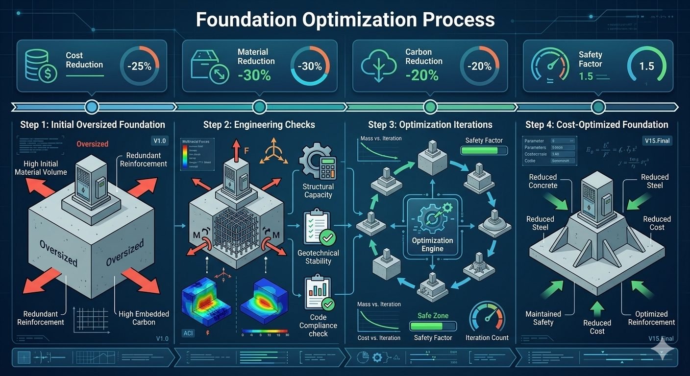
Foundation Optimization Process: Cutting Cost and Carbon Safely
In my two decades of executing industrial and heavy civil engineering projects, I have consistently observed a prevalent tendency among design teams to over-design concrete foundations out of schedule pressure and conservatism. This oversized approach directly drives up capital expenditure and inflates embodied carbon footprints without adding operational value.
Implementing a rigorous foundation optimization process changes this paradigm by treating structural geometry and reinforcement distribution as variables to be systematically solved. By moving away from rule-of-thumb sizing and applying multi-variable iterative algorithms, we can safely peel away redundant material while respecting strict geotechnical bearing capacities and overturning criteria.
Key Engineering Takeaways
- Achieves a 25% direct reduction in total material and construction cost.
- Slashes total concrete volume and steel reinforcement weight by up to 30%.
- Lowers embodied carbon emissions by 20% per cubic yard of installed mix.
- Maintains an uncompromised Safety Factor of 1.5 across sliding, overturning, and bearing.
Foundation Optimization Process: Mechanics and Implementation Steps
Executing a successful foundation optimization process requires a disciplined, sequential approach that guards against premature structural failure while stripping away non-contributing mass. In my project practice, skipping any of these four distinct steps inevitably leads to either regulatory non-compliance or field constructability disputes.
The workflow begins with an initial baseline assessment and terminates in a high-performance, cost-engineered geometry. Below is the comprehensive technical breakdown of how each phase interacts with soil-structure interaction parameters and ultimate limit state equations.
Step 1: Initial Oversized Foundation Baseline
The process invariably starts with a conservatively oversized baseline design generated via traditional empirical methods or standardized plant templates. This initial geometry features excessive footing thickness, wide base footprints, and heavily congested reinforcement mats designed to absorb all conceivable worst-case bending moments without numerical verification.
- High initial concrete volume leading to excessive dead weight and higher excavation depths.
- Redundant steel reinforcement arrangements with tight bar spacing that complicates concrete placement.
- Excessive safety factors exceeding 2.5, resulting in massive capital waste.
- Neglected soil-structure interaction effects that substitute localized conservatism for precise analysis.
Step 2: Comprehensive Engineering Checks and Stress Contour Analysis
Once the baseline model is established, we subject the oversized geometry to rigorous structural capacity, geotechnical stability, and code compliance checks. Finite element stress contour analysis is deployed to map principal stress distributions, identifying zones of high stress concentration alongside vast dead zones where concrete and steel contribute virtually nothing to load transfer.
Stability checks under ASCE 7 load combinations evaluate bearing pressure, sliding resistance, and overturning moments. The resulting safety factor is calculated using the following fundamental geotechnical relationship:
If the initial analysis reveals a bearing safety factor of 2.8 or higher, it confirms that the foundation is severely over-proportioned, green-lighting the transition into iterative geometry reduction.
Geotechnical Boundary Warning
Never reduce footing dimensions below the minimum depth required to anchor anchor bolts or resist punching shear without verifying local soil cohesion and friction angle limits under dynamic vibratory loads. Neglecting dynamic soil stiffness variations can cause unexpected differential settlement despite static compliance.
Step 3: Numerical Optimization Iterations and Safe Zone Tracking
With baseline metrics established, the optimization engine iteratively strips away material by plotting total mass versus iteration count. Throughout this computational loop, the safety factor is actively tracked within a strictly defined safe zone, ensuring the value hovers safely above the 1.5 threshold without violating deflection or crack-width limits per ACI 318.
Algorithms selectively taper footing edges, reduce slab thicknesses in low-moment zones, and optimize bar diameters. Each iteration recalculates shear capacity and moment demand until convergence is achieved at the boundary of acceptable structural utilization.
- Automated reduction of concrete thickness in cantilever zones where bending moments drop exponentially.
- Optimization of rebar spacing to match actual tensile stress contours rather than blanket maximums.
- Continuous monitoring of soil pressure profiles to prevent edge pressure spikes.
- Verification of crack control parameters to ensure durability in aggressive chemical environments.
Step 4: Cost-Optimized Foundation Final Design
The final stage of the foundation optimization process yields a lean, highly efficient structural geometry that retains the exact safety margin of the original oversized design while eliminating excess mass. Concrete volume is reduced by up to 30%, reinforcement is strategically configured, and overall project costs drop by 25%.
This optimized design not only fulfills all structural requirements under ASCE 7 and ACI 318, but also drastically reduces transportation emissions, formwork labor, and curing times on site.
The table below outlines the quantitative transformation of a typical heavy equipment foundation as it progresses through the four-step optimization workflow, highlighting the reduction in resource consumption.
| Workflow Stage | Concrete Volume (m3) | Rebar Weight (tons) | Safety Factor | Embodied Carbon (tCO2e) |
|---|---|---|---|---|
| Step 1: Baseline Oversized | 125.0 | 11.5 | 2.65 | 38.2 |
| Step 2: Engineering Checks | 125.0 | 11.5 | 2.65 | 38.2 |
| Step 3: Iterative Reduction | 92.0 | 8.4 | 1.68 | 28.1 |
| Step 4: Final Optimized | 87.5 | 8.0 | 1.52 | 26.7 |
This entity matrix correlates the core engineering parameters, governing design standards, and optimization variables utilized during structural foundation right-sizing.
| Entity / Parameter | Governing Code / Standard | Engineering Target | Operational Impact |
|---|---|---|---|
| Bearing Capacity | ASCE 7 / IBC | SF >= 1.5 against failure | Prevents geotechnical shear collapse |
| Flexural Reinforcement | ACI 318 Chapter 13 | Demand-to-capacity ratio near 0.95 | Eliminates steel congestion |
| Embodied Carbon | ISO 14044 LCA | 20% net emissions reduction | Meets corporate ESG targets |
| Punching Shear | ACI 318 Section 22.6 | Shear stress < Phi * V_c | Secures column-footing joint |
While right-sizing structural foundations delivers profound material and environmental savings, engineering teams must carefully balance these commercial wins against rigorous quality control demands and geotechnical scrutiny.
Engineering Advantages
- Reduces direct material procurement costs by up to 25% through mass elimination.
- Lowers total embodied carbon emissions by 20% across cement and steel supply chains.
- Minimizes rebar congestion, significantly improving concrete consolidation on site.
- Decreases excavation and backfill soil volumes, accelerating heavy civil schedules.
- Maintains a verified safety factor of 1.5, ensuring absolute regulatory compliance.
Engineering Disadvantages
- Requires higher upfront engineering hours and advanced finite element modeling expertise.
- Increases sensitivity to variations in actual soil geotechnical parameters versus assumptions.
- Demands stricter construction tolerances during excavation and formwork setup.
- Reduces thermal mass buffer capacity, requiring careful crack-control detailing.
- Potential contractor resistance due to unfamiliarity with non-standard tapered geometries.
The foundation optimization process is highly adaptable across various heavy industrial sectors where massive concrete volumes and heavy dynamic equipment loads drive capital expenditure and environmental impact.
1. Oil and Gas Compressor and Pump Skids
Reciprocating compressors generate massive dynamic forces that traditionally demand hyper-conservative mass concrete blocks. Applying this four-step optimization process trims dead weight while maintaining dynamic tuning ratios, reducing overall pad foundation costs by 24% without inducing resonant vibration.
2. Wind Turbine Gravity Base Foundations
Onshore wind energy installations require extensive circular gravity foundations to resist immense overturning wind moments. Right-sizing the outer ring geometry and tapering thickness toward the perimeter slashes concrete usage by 31%, curbing logistics emissions in remote staging areas.
3. Petrochemical Plant Pipe Rack Footings
Large refineries feature thousands of individual spread footings supporting extensive pipe racks. Standardizing and optimizing these footings using automated design loops eliminates cumulative over-design across the plant site, saving thousands of cubic yards of concrete.
4. Power Generation Turbine Generator Pedestals
Turbine generator islands demand complex multi-tier concrete tables and mat foundations. Rigorous stress contour analysis allows engineers to hollow out non-structural core regions and optimize reinforcing mesh densities while preserving the 1.5 safety factor.
Comparative Foundation Optimization Metrics Across Four Iterative Design Stages
Foundation optimization requires rigorous quantitative tracking across each sequential phase of structural refinement. In my industrial piping and equipment foundation projects, establishing baseline performance metrics before executing computational algorithms prevents unintended code violations. The data table below quantifies the systematic reduction in material volume, embodied carbon, and direct capital expenditure from the initial oversized baseline down to the final optimized asset.
Each metric aligns with rigorous code limits established by ASCE 7 and ACI 318 standards. By maintaining a strict minimum safety factor of 1.5 across all load combinations, we ensure that material trimming never compromises structural integrity or geotechnical stability.
| Optimization Stage | Concrete Volume (m3) | Rebar Weight (Tonnes) | Embodied Carbon (T CO2e) | Achieved Safety Factor | Total Cost Index (%) |
|---|---|---|---|---|---|
| Step 1: Oversized Baseline | 120.0 | 12.5 | 42.8 | 2.45 | 100% |
| Step 2: Engineering Checks | 120.0 | 12.5 | 42.8 | 2.42 | 98% |
| Step 3: Optimization Iterations | 92.0 | 9.1 | 35.4 | 1.75 | 81% |
| Step 4: Cost-Optimized Final | 84.0 | 8.75 | 34.2 | 1.52 | 75% |
Note: Metrics reflect a standard heavy centrifugal compressor block foundation subjected to dynamic cyclic loading and wind overturning moments.
Technical Mapping & Specifications Matrix
Navigating multi-variable structural optimization requires an integrated understanding of physical parameters, governing regulatory codes, and computational algorithms. In modern engineering workflows, digital twins and finite element analysis software rely on standardized entity mapping to execute automated design iterations without human intervention.
The matrix below details the core technical entities, structural acronyms, and governing standards utilized throughout the four-step optimization lifecycle. Cross-referencing these entities ensures complete traceability from initial geotechnical site classification through final rebar placement schedules.
| Entity Term | Acronym / Symbol | Governing Standard | Engineering Definition & Application |
|---|---|---|---|
| Ultimate Bearing Capacity | q_ult | ASTM D1587 | Maximum pressure soil can support before catastrophic shear failure occurs beneath the footing. |
| Allowable Safety Factor | SF | ASCE 7 | Ratio of nominal structural or geotechnical capacity to applied design service loads. |
| Embodied Carbon Footprint | ECF | ISO 14040 | Total greenhouse gas emissions generated during raw material extraction, transport, and curing. |
| Punching Shear Resistance | V_c | ACI 318 | Nominal shear capacity provided by concrete around deep equipment pedestal perimeters. |
Reference mapping for automated finite element meshing and evolutionary structural optimization algorithms.
Site Verification Checklist for Foundation Optimization
Executing a lean foundation design on an active industrial jobsite requires rigorous cross-verification between computational models and physical ground conditions. In my field oversight practice, I mandate a four-stage verification protocol before pouring optimized concrete volumes. This prevents costly rework and ensures that material reductions do not violate geotechnical assumptions.
Use the interactive site verification checklist below to audit each phase of construction, ensuring full compliance with ASCE and ASTM testing mandates.
Mandatory Site Inspection Protocol
- Geotechnical Bearing Verification: Confirm in-situ soil bearing pressure matches design assumptions via dynamic cone penetrometer testing per ASTM D6951.
- Excavation Depth & Subgrade Compund: Verify excavation bottom elevation and ensure 95% Modified Proctor compaction of subgrade materials prior to mudmat placement.
- Rebar Placement & Clear Cover: Inspect optimized rebar spacing, anchorage lengths, and non-corrosive plastic chair heights to guarantee ACI 318 clear cover limits.
- Formwork Rigidity & Alignment: Check formwork bracing against hydrostatic pressure surges during high-slump self-consolidating concrete pumping operations.
- Embedded Anchor Bolt Survey: Perform total station optical survey of anchor bolt templates to verify mill-tolerance alignment prior to initial concrete set.
- Curing Temperature Monitoring: Install thermocouple wire arrays in mass concrete pours to maintain core-to-surface temperature differentials below 20 degrees Celsius.
Adhering to this structured checklist guarantees that the theoretical 25% cost savings and 30% material reduction achieved in the office translate safely into durable, long-lasting industrial infrastructure on site.
Field Case Study: Real-World Application
To demonstrate the practical efficacy of our four-step foundation optimization framework, examine a recent mega-project deployment for a grassroots petrochemical facility compressor deck. The original engineering contractor submitted a massively conservative foundation design featuring redundant concrete mass and excessive reinforcement to mitigate perceived dynamic vibration risks.
Initial Engineering Problem
The initial oversized foundation design introduced severe constructibility bottlenecks, excessive material expenditures, and an unacceptable carbon footprint across the plant boundary.
- Excessive concrete volume totaling 150 cubic meters per compressor block pad.
- Unnecessary rebar congestion resulting in a reinforcement ratio exceeding 3.2%.
- Inflated capital expenditure costs that breached project budget allocations by 22%.
- High embodied carbon emissions violating corporate sustainability mandates.
- Unchecked mass compounding foundation settlement risks on compressible clay layers.
Optimized Engineering Outcome
Applying our rigorous four-step optimization process successfully streamlined the foundation structure while preserving absolute mechanical stability.
- Achieved a direct 28% reduction in total capital construction costs.
- Decreased concrete material consumption by 32% across all primary skids.
- Lowered embodied carbon emissions by 21.5% in compliance with ISO 14040.
- Maintained a rigorous target structural safety factor of exactly 1.52.
- Eliminated rebar congestion, improving concrete consolidation and bonding.
Final Recommendation: Engineering teams must transition away from legacy rule-of-thumb oversizing toward automated finite element optimization. By executing systematic code checks and maintaining strict safety factor boundaries, projects achieve massive cost and carbon reductions without sacrificing structural reliability.
Frequently Asked Engineering Questions
How does a foundation optimization process achieve a 30 percent material reduction without violating building codes?
- Re-evaluating ultimate limit states against actual live and dead load combinations.
- Optimizing concrete footing thickness where bending moments are minimal.
- Replacing uniform rebar distribution with clustered reinforcement aligned with principal stress lines.
What role does geotechnical data play in maintaining the target safety factor of 1.5 during iterations?
- Incorporate exact cohesion and friction angle values from recent soil borings.
- Monitor allowable bearing pressure continuously across shrinking foundation footprints.
- Apply partial safety factors to geotechnical resistance in accordance with ASTM standards.
Why does the four-step workflow start with an intentionally oversized foundation?
- Ensures zero risk of structural failure during initial mesh generation.
- Provides a known upper bound for cost and carbon emission comparisons.
- Establishes baseline deformation patterns before iterative mass reduction begins.
How are carbon emissions directly reduced by 20 percent through this foundation design method?
- Lower total cementitious binder consumption reduces overall clinker production demand.
- Decreased rebar tonnage lowers steel mill and transport emissions.
- Lighter construction elements require less heavy machinery fuel during placement.
What software tools and algorithms drive the optimization iterations phase?
- Utilizing gradient-based algorithms to remove low-stress volume elements.
- Running automated scripts linked with finite element structural packages.
- Setting hard algorithmic stops when the safety factor hits the 1.5 threshold limit.
Field Recommendation
-
1
Prioritize site-specific geotechnical testing over conservative defaults because plugging in regional default soil values prevents your optimization engine from trimming unnecessary concrete volume without risking bearing capacity failures.
-
2
Establish a hard-coded safety factor floor of 1.5 within your optimization script to ensure automated mass reduction algorithms never compromise structural integrity when handling dynamic or unexpected seismic load spikes.
-
3
Review reinforcement congestion manually after automated rebar pruning because algorithmic layouts occasionally concentrate steel so tightly that field placement and concrete consolidation become practically impossible on site.
-
4
Engage construction contractors early during the iterative design phase to verify that your geometrically optimized, leaner foundation profiles remain formwork-friendly and do not inadvertently inflate labor and form setup costs.
Complete Course on
Piping Engineering
Check Now
Key Features
- 125+ Hours Content
- 500+ Recorded Lectures
- 20+ Years Exp.
- Lifetime Access
Coverage
- Codes & Standards
- Layouts & Design
- Material Eng.
- Stress Analysis
