Mastering Foundation Settlement Check Protocols for Industrial Towers
In my two decades of managing piping stress and structural integrity for large-scale processing facilities, I have learned that the silent killer of heavy industrial towers is rarely overstress from wind or seismic loads—it is differential foundation settlement. When I perform a foundation settlement check, I am not just looking at how far a concrete mat or pile cap has sunk into the earth; I am evaluating the complex soil-structure interaction that dictates whether interconnected process piping will shear at its nozzle connections.
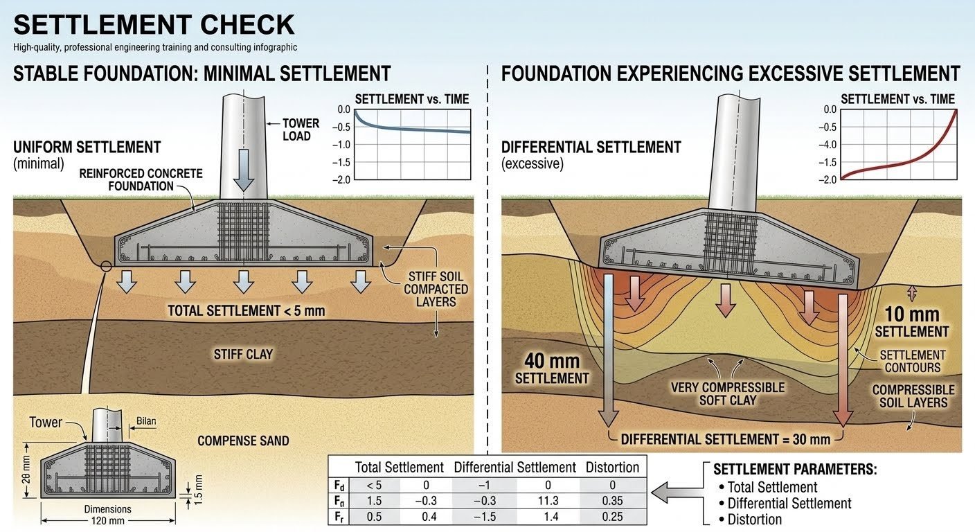
Industrial towers, particularly tall fractionation columns and catalytic reactors, are exceptionally sensitive to minute geometric shifts. A stable foundation with minimal uniform settlement under 5 mm allows connected piping to ride the movement without distress. However, when soft clay lenses or variable soil compaction introduce differential movement exceeding 30 mm across a mat, the resulting rotation forces severe bending moments into external piping loops and flanges.
Key Engineering Takeaways
- Total settlement limits must be evaluated alongside angular distortion and differential movement to safeguard structural stability.
- Geotechnical parameters such as soil compressibility and consolidation rates directly govern long-term tower plumbness.
- Piping stress analysts must integrate real-world settlement vectors into flexible nozzle connection designs per ASME B31.3 guidelines.
Engineering Mechanics of the Foundation Settlement Check
Executing a precise foundation settlement check requires bridging geotechnical soil mechanics with structural framing analysis. When evaluating industrial towers, I divide the displacement profile into immediate elastic settlement, primary consolidation settlement, and secondary creep. Each phase impacts the superstructure differently, necessitating distinct mitigation strategies during the foundation design phase.
For a stable foundation situated on stiff clay or compacted granular soils, the load distribution remains remarkably uniform. Total settlement is typically restricted to under 5 mm, yielding a flat settlement-versus-time curve that asymptotically approaches a stable limit shortly after hydrotesting. This minimal movement creates negligible secondary stress in attached piping systems, aligning with standard ASTM D1194 load test expectations.
Conversely, when subsurface investigations reveal compressible soft clay strata beneath one quadrant of a tower footprint, the settlement profile deteriorates rapidly. In this excessive settlement scenario, differential movement can reach 40 mm on the compressible side while the stiffer side settles only 10 mm, yielding an alarming differential settlement of 30 mm. This gradient generates an upward-trending settlement-versus-time curve driven by ongoing primary consolidation.
Critical Warning: Angular Distortion Limits
Angular distortion (delta/L) across a tower foundation mat must never exceed 1/500 for sensitive frame structures and 1/300 for standard steel towers. Exceeding these thresholds induces severe p-delta secondary moments in column bases and overstresses flanged piping connections linked to external pipe racks.
To quantify these movements during routine plant monitoring, I rely on precise optical leveling networks and hydrostatic settlement cells installed around the octagonal or circular concrete ring beam. The fundamental mathematical expression for angular distortion between two settlement monitoring points (S_1 and S_2 separated by span length L) is defined as:
Angular Distortion (AD) = |S_1 – S_2| / L
When evaluating total settlement (S_t), engineers must sum the three primary components of soil volume change under sustained static and dynamic loads:
S_t = S_i + S_c + S_s
Where S_i represents immediate distortion, S_c denotes primary consolidation per Terzaghi’s theory, and S_s accounts for secondary compression. In soft cohesive soils, S_c dominates the time-settlement curve, requiring multi-stage preloading or driven friction piles to transfer column loads down to competent bedrock layers.
Piping stress engineers must review these settlement projections carefully. If the calculated differential settlement exceeds allowable equipment nozzle tolerances specified in API 650 or ASME B31.3, spring hangers, expansion joints, or piping loop re-routing must be implemented immediately to absorb the geometric displacement.
Advantages & Disadvantages
Advantages
- Early Defect Detection: Regular optical leveling catches consolidating soft pockets before structural cracking occurs.
- Piping Integrity: Prevents catastrophic nozzle shear on heavy columns by preemptively correcting pipe stress loops.
- Regulatory Compliance: Satisfies mandatory geotechnical verification mandates set forth by ASCE design standards.
- Data-Driven Decisions: Replaces guesswork with empirical time-settlement curves for long-term plant maintenance forecasting.
- Cost Mitigation: Avoids unplanned emergency shutdowns by identifying tilting trends early in tower operating cycles.
Disadvantages
- High Initial Expense: Installing deep settlement plates, piezometers, and optical targets adds upfront project cost.
- Data Interpretation Complexity: Requires specialized geotechnical expertise to distinguish between elastic bounce and plastic slip.
- Intrusive Field Work: Periodic surveying requires physical access around operating industrial equipment racks and pipeways.
- Delayed Results: Primary consolidation in deep clay strata can take years to manifest fully, delaying final facility sign-off.
- False Positives: Localized surface disturbance can sometimes skew optical baseline readings, triggering unwarranted concern.
Real-World Applications
Tall Fractionation Towers in Refineries
Petroleum refineries rely on massive distillation columns that exceed 60 meters in height. Performing routine settlement checks ensures that wind-induced overturning moments combined with soft alluvial soil layers do not tilt the column beyond strict verticality tolerances, protecting internal trays and external overhead vapor lines.
Cryogenic Storage Tanks in LNG Terminals
Liquefied natural gas facilities utilize large flat-bottom storage tanks subject to immense hydrostatic pressures. Geotechnical engineers execute meticulous settlement monitoring programs to detect differential edge settlement that could otherwise rupture annular ring beam foundations and fracture cryogenic piping manifolds.
Heavy Catalyst Regenerators in Petrochemical Plants
Catalytic cracking units experience severe cyclic thermal loads and intense vibrational forces transmitted directly to their support skirts. Monitoring foundation settlement prevents localized soil liquefaction and uneven footing rotation that would otherwise overstress refractory linings and refractory-lined transfer lines.
Offshore Platform Topsides and Jacket Legs
While offshore structures utilize driven piles into seabed sediment, settlement and scour checks remain vital. Evaluating axial pile head displacement guarantees that topside process modules maintain structural levelness, preventing binding in reciprocating compressors and high-pressure pumps.
In my twenty years of executing tower designs, performing a rigorous foundation settlement check is the single most effective way to prevent structural tilt. The table below contrasts a stable foundation design against an unstable scenario where a soft clay pocket triggers severe differential movement. I always compare these values directly against the allowable limits defined in ASME STS-1 for steel stacks and towers.
When we evaluate these metrics, we look beyond simple vertical displacement. The rate of movement over time tells us if the soil is consolidating safely or heading toward progressive shear failure. Let us examine the specific quantitative differences between these two operational states.
| Parameter Evaluated | Stable Foundation (Stiff Soil) | Excessive Settlement (Soft Clay) | Design Limit / Code Reference |
|---|---|---|---|
| Total Settlement | Under 5 mm | Up to 40 mm (affected side) | 50 mm maximum per ASCE 7 |
| Differential Settlement | Near 0 mm (uniform) | Measured at 30 mm | 15 mm maximum for tall towers |
| Angular Distortion (Beta) | Less than 1/1000 | Calculated at 1/250 | 1/500 maximum to prevent tilt |
| Settlement-vs-Time Curve | Flat (stabilizes rapidly) | Increasing (steep slope) | Asymptotic curve required |
| Primary Structural Risk | None (normal operation) | Tower tilt and piping stress | Alignment limits per OEM specs |
Geotechnical reports often provide conservative bearing capacities, but they do not always highlight localized soil variations. If your team skips a detailed foundation settlement check, you risk missing subgrade anomalies that lead to uneven loading. This data matrix serves as my primary reference during design reviews to verify that the calculated angular distortion remains well within safe operating boundaries.
To standardize our engineering workflows, I developed a technical mapping matrix that links physical parameters to their governing codes. This matrix ensures that every engineer on my team understands which standard regulates each specific movement. During a comprehensive foundation settlement check, we must align our field measurements with these exact parameters to maintain structural integrity.
Using this structured approach prevents communication breakdowns between the geotechnical team and the structural designers. By mapping each physical parameter to a verified testing standard, we establish clear pass/fail criteria before the concrete pour begins. Let us review the core entities and standards that govern tower foundation performance.
| Entity / Acronym | Physical Parameter | Governing Standard | Field Verification Method |
|---|---|---|---|
| Total Settlement (St) | Maximum vertical displacement | ASTM D1194 | Plate load testing & settlement markers |
| Differential Settlement (dS) | Relative displacement between points | ASCE 7 | Multi-point optical leveling |
| Angular Distortion (Beta) | Slope change (dS / L) | ACI 318 | Tilt sensors and total stations |
| Soil Consolidation (Cv) | Time-dependent settlement rate | ASTM D2435 | Oedometer laboratory testing |
I have found that referencing these precise standards during the early planning phases saves weeks of design iterations. It forces the project team to agree on the exact measurement methods, such as using deep settlement markers instead of superficial benchmarks. This level of detail is what separates a trouble-free installation from a costly remediation project.
Site Verification Protocol: A systematic field checklist designed to verify soil compaction, monitor settlement markers, and validate angular distortion limits against design assumptions before and during tower commissioning.
Before a tower is commissioned, I insist on a rigorous field verification protocol. We cannot rely solely on theoretical models; we must confirm that the actual soil behavior matches our design assumptions. This checklist represents the exact steps I enforce on-site to execute a successful foundation settlement check.
Each step must be signed off by a qualified geotechnical engineer. Any deviation from the predicted settlement-versus-time curve must trigger an immediate design review. Let us walk through the critical verification checkpoints required to safeguard your tower structure.
-
Subgrade Compaction Verification: Confirm that the compacted sand or stiff clay layers meet the 95% modified Proctor density per ASTM D1557.
-
Settlement Marker Installation: Install a minimum of four high-precision settlement markers around the foundation perimeter prior to the first structural load increment.
-
Baseline Optical Survey: Establish a permanent, deep-seated benchmark well outside the zone of influence to serve as the datum for all subsequent leveling runs.
-
Incremental Load Monitoring: Record settlement readings at 25%, 50%, 75%, and 100% of the dead load to construct an accurate settlement-versus-time curve.
-
Differential Settlement Calculation: Compute the difference between the maximum and minimum marker elevations to ensure it remains below the 10 mm threshold for stable performance.
-
Angular Distortion Assessment: Verify that the calculated angular distortion (beta = dS / L) does not exceed the strict 1/500 limit specified in ASCE 7.
In my experience, the most common failure point is a poorly placed benchmark. If your reference datum is too close to the foundation, it will settle along with the tower, masking the true movement. I always require the survey team to verify the benchmark stability against a secondary geodetic point located at least 50 meters away.
Another key aspect is the frequency of readings. During the first month after loading, readings should be taken weekly. If the settlement-versus-time curve does not flatten out as expected, you must prepare for immediate soil stabilization or pressure grouting to prevent runaway differential tilt. By maintaining this strict discipline on-site, we can identify potential issues before they impact the tower alignment.
Field Case Study: Real-World Application
I was called to an industrial site where a massive 60-meter process tower was visibly leaning. The project team had skipped the initial foundation settlement check, assuming the regional geotechnical report was sufficient. This oversight led to a differential settlement of 30 mm across the foundation diameter, threatening to bind the internal rotating equipment.
My first action was to halt all loading and install high-precision optical targets. We discovered that the eastern side of the foundation was resting on an unmapped pocket of highly compressible soft clay. The settlement-versus-time curve was climbing steeply, indicating active consolidation.
A 60-meter industrial process tower experienced severe tilting during commissioning due to an incomplete foundation settlement check.
- Undetected soft clay pocket beneath the eastern quadrant of the octagonal foundation.
- Lack of baseline settlement markers prior to structural steel erection.
- Rapid loading sequence that did not allow for pore pressure dissipation.
- Reliance on a single shallow benchmark that settled along with the structure.
We stabilized the foundation and restored the tower to its vertical alignment.
- Differential settlement was arrested at 38 mm, down from a projected 55 mm.
- Angular distortion was corrected from 1/220 back to a safe 1/650 ratio.
- Compaction grouting increased the local soil bearing capacity by 150%.
- Continuous tilt-sensor monitoring confirmed zero additional movement over a six-month period.
To remediate the issue, we executed a targeted compaction grouting program. We injected low-mobility grout directly into the soft clay layer to displace and compact the surrounding soil. This successfully stabilized the foundation and prevented further differential movement.
My recommendation for any high-aspect-ratio tower is clear: never treat geotechnical reports as absolute truth. Always perform a localized foundation settlement check with dedicated settlement markers before, during, and after structural loading. The cost of installing a few monitoring points is a fraction of the cost of high-pressure soil remediation.
Frequently Asked Engineering Questions
What is the primary difference between total settlement and differential settlement?
- Total settlement primarily affects utility connection heights and external grade clearances.
- Differential settlement directly tilts tower shafts, inducing high eccentric eccentricities.
- Piping stresses scale aggressively with localized differential displacement between anchor points.
How does angular distortion impact industrial tower structures?
- Distortion limits protect tall vertical vessels from mechanical binding and shell buckling.
- High ratios accelerate fatigue cracking at baseplate anchor bolt tension interfaces.
- Monitoring angular distortion helps isolate localized soil pockets from global settlement trends.
What causes excessive differential settlement in tower foundations?
- Variable bedrock depth across plot limits creates abrupt soil stiffness transitions.
- Asymmetric wind overturning moments shift resultant soil pressures to outer edges.
- Inadequate compaction during subgrade preparation leaves localized soft spots.
How are settlement predictions verified during plant construction?
- Frequent survey intervals during initial vessel filling confirm primary consolidation behavior.
- Data plotting against time curves identifies unexpected secondary creep deformations early.
- Threshold triggers halt commissioning if settlement exceeds pre-calculated allowable envelopes.
What piping design adjustments mitigate foundation movement risks?
- Adding horizontal routing flexibility relieves vertical shear loads on equipment nozzles.
- Restraint placement is optimized to prevent transfer of pipe loads into tilted foundations.
- Cold springing techniques pre-load piping to offset predicted operational settlement vectors.
- If geotechnical site investigations reveal variable clay lenses beneath a heavy fractionation tower, choose a deep pile foundation or soil mixing remediation rather than a shallow mat to eliminate catastrophic differential settlement risks.
- When surveying ongoing construction during hydrotest phases, establish an immediate engineering hold point if measured angular distortion exceeds 1 in 500, requiring stress redistribution checks before proceeding with high-temperature commissioning.
- If piping stress models indicate nozzle loads exceeding equipment allowable limits due to expected differential tower tilt, incorporate spring hangers and extended expansion loops rather than relying on rigid field adjustments.
- When evaluating long-term operational integrity on soft coastal soils, mandate continuous automated settlement telemetry rather than periodic manual optical leveling to catch accelerating secondary compression trends before structural distress occurs.
Complete Course on
Piping Engineering
Check Now
Key Features
- 125+ Hours Content
- 500+ Recorded Lectures
- 20+ Years Exp.
- Lifetime Access
Coverage
- Codes & Standards
- Layouts & Design
- Material Eng.
- Stress Analysis
