Solar Plant Electrical Installation Execution and Commissioning Workflows
In my two decades of managing utility-scale energy projects, I have learned that the success of a photovoltaic facility hinges entirely on structured field execution. When dealing with complex multi-megawatt installations, splitting our workforce into targeted units is not merely an option—it is a strict necessity for safety and velocity.
By segregating our personnel into specialized DC, AC, and controls divisions, we eliminate cross-trade interference and streamline quality control. Let us examine the exact architectural frameworks required to transition a barren tract of land into an operational energy asset.
Key Execution Takeaways:
- Strict segregation of DC, AC, and Controls scopes prevents inter-trade rework and safety hazards.
- Systematic milestone tracking from module installation to Commercial Operation Date (COD).
- Rigorous adherence to international standards including IEEE, NFPA, and IEC codes.
- Advanced SCADA integration guarantees seamless utility grid synchronization and telemetry.
Solar Plant Electrical Installation Methodologies and Team Deployment
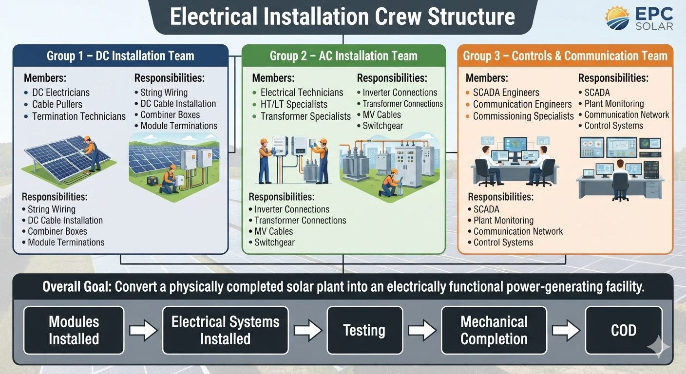
Executing a utility-scale solar project requires synchronizing diverse technical disciplines. In my experience, separating the workforce into three distinct operational groups protects project schedules and ensures high-voltage integrity. Each group operates with specialized tools, distinct safety protocols, and specialized testing equipment to guarantee compliance with IEC 62446 standards for photovoltaic system testing and documentation.
Group 1: DC Installation Team Architecture
The foundation of our power generation loop begins at the photovoltaic module level. The DC Installation Team consists of certified DC Electricians, Cable Pullers, and Termination Technicians. Their primary mandate involves string wiring, DC cable routing, combiner box installation, and module-level terminations.
- String Wiring & Management: Routing PV wire harnesses along torque tubes while maintaining minimum bending radius limits to prevent micro-cracks in silicon wafers.
- Combiner Box Placement: Mounting string combiner boxes on racking structures or dedicated pedestals, ensuring proper NEMA 4X / IP66 environmental sealing against moisture ingress.
- Polarity & Voltage Verification: Conducting open-circuit voltage (Voc) and short-circuit current (Isc) testing on every home-run string prior to main busbar connection.
Critical Field Warning: DC Arc-Flash Hazard
DC circuits present severe continuous-arc hazards because unlike AC power, there is no natural zero-crossing point. Never disconnect string connectors under load. All technicians must utilize specialized insulated tools rated for 1500VDC in strict compliance with OSHA 1910.333 safety-related work practices.
Group 2: AC Installation Team and Power Conversion
Once the direct current is successfully gathered at the combiner arrays, it is handed over to the AC Installation Team. Comprising Electrical Technicians, High-Tension (HT) and Low-Tension (LT) Specialists, and Transformer Technicians, this group manages the conversion of DC power into synchronized utility-grade alternating current.
- Inverter Integration: Securing central or string inverter skids, terminating heavy-gauge AC output cables, and verifying internal phase rotation alignment.
- Transformer Connections: Bolting up medium-voltage bushings, establishing rigorous grounding grids, and performing dielectric oil breakdown testing per ASTM D877 standards.
- Switchgear and Protection Relays: Commissioning vacuum circuit breakers, configuring overcurrent relays, and verifying trip-curve settings with secondary injection test sets.
Group 3: Controls and Communication Team
The nervous system of the utility plant is installed and calibrated by our third division. The Controls and Communication Team brings together SCADA Engineers, Network Specialists, and Commissioning Engineers to establish complete plant observability and remote control capabilities.
- SCADA Architecture: Deploying redundant industrial servers, fiber optic backbone rings, and weather station meteorological towers measuring plane-of-array irradiance and ambient temperature.
- Communication Network Setup: Configuring Modbus TCP, DNP3, and IEC 61850 protocol gateways to communicate seamlessly with utility dispatch centers.
- Plant Control Loops: Calibrating active power curtailment, reactive power injection, and automatic generation control (AGC) response loops.
Milestone Progression to Commercial Operation Date (COD)
The collaborative effort of all three specialized teams drives the plant through rigid contractual gates. We progress sequentially from mechanical completion of module structures to comprehensive electrical system installations, rigorous pre-commissioning tests, mechanical completion certification, and finally the Commercial Operation Date. Maintaining this linear workflow guarantees zero shortcuts and total quality assurance.
Operational Advantages
- Targeted Skill Mastery: Technicians focus exclusively on their core expertise, drastically reducing installation errors and rework rates.
- Enhanced Safety Compliance: Clear demarcation of DC high-voltage zones and AC switchgear zones minimizes accidental contact and arc-flash exposure.
- Parallel Workstreams: DC, AC, and controls teams can execute tasks simultaneously in different sectors of a large utility site.
- Streamlined Quality Audits: Supervisors can easily verify workmanship milestones against specific trade checklists prior to handover.
- Accelerated Commissioning: Pre-tested subsystems integrate smoothly during final plant-wide energization procedures.
Operational Disadvantages
- High Coordination Overhead: Requires meticulous scheduling by the general superintendent to prevent trade congestion in tight inverter pads.
- Resource Allocation Friction: Specialized tools and equipment must be shared or duplicated across multiple independent team units.
- Communication Gaps: Handoffs between Group 1 (DC) and Group 2 (AC) require rigorous sign-off sheets to prevent boundary disputes.
- Training Complexity: Onboarding multi-tier specialized personnel takes longer than hiring generalized electrical labor pools.
- Mobilization Costs: Maintaining dedicated leads for each distinct group increases initial administrative site overhead.
Utility-Scale Ground-Mounted Solar Parks
On massive 500MW desert solar installations stretching across thousands of acres, segregated electrical teams are essential for maintaining pace. Group 1 deploys miles of DC home-run cables across tracker rows, while Group 2 sets massive central inverter skids and medium-voltage step-up transformers. Group 3 simultaneously installs fiber optic rings to connect every power conversion station back to the central control building.
Commercial and Industrial Rooftop Arrays
Complex C&I rooftop installations present severe logistical constraints regarding roof loading and penetration limits. Specialized DC installation crews handle ballasted racking wire management without compromising roof membranes, while AC specialists tie string inverters directly into existing facility switchgear rooms under strict shutdown windows coordinated with plant operations.
Hybrid Solar and Battery Energy Storage Systems
Integrating utility solar farms with large-scale BESS facilities requires advanced coordination between DC solar arrays, bidirectional power conversion systems, and complex battery management networks. The controls team implements sophisticated SCADA logic to manage seamless charging and discharging cycles while ensuring compliance with stringent utility interconnection grid codes.
Remote Off-Grid Microgrid Facilities
In remote mining or island microgrids where solar generation is paired with diesel backup generators, precise electrical installation prevents catastrophic blackouts. The AC and controls specialists coordinate black-start capabilities, load-shedding schemes, and seamless governor synchronization to maintain continuous industrial power reliability without grid support.
Solar Plant Electrical Parameters and Team Responsibilities
In industrial solar engineering, successful grid synchronization relies on strict adherence to equipment ratings, cable sizing parameters, and distinct jurisdictional boundaries among the three specialized installation crews. The table below outlines the primary technical responsibilities, voltage tiers, and governing IEC standards that dictate daily execution on site.
Review these specifications to ensure your engineering team correctly coordinates DC string voltages, medium-voltage transformer taps, and SCADA communication protocols before mechanical completion occurs.
| Installation Team | Primary Scope | Voltage Class | Governing Standard | Milestone Target |
|---|---|---|---|---|
| DC Installation Team | String Wiring & Combiner Boxes | Up to 1500V DC | IEC 62548 | Modules Installed |
| AC Installation Team | Inverters & Step-Up Transformers | 33kV / 66kV AC | IEEE 1547 | Electrical Systems Installed |
| Controls & Comm Team | SCADA & Plant Monitoring | 24V DC / Fiber Optic | IEC 61850 | Testing & Commissioning |
Table 1: Comprehensive breakdown of team duties, voltage ratings, and associated electrical milestones for utility-scale PV farms.
Technical Mapping & Specifications Matrix
Maintaining traceability across complex electrical architectures requires a structured entity mapping model. The matrix below defines the core engineering acronyms, hardware classifications, and verification protocols utilized by our multidisciplinary teams during construction and testing phases.
Use this matrix to standardize technical vocabulary across contractor submittals, testing reports, and utility interconnection documentation prior to achieving Commercial Operation Date (COD).
| Entity Acronym | Full Technical Designation | Operational Parameter | Compliance Reference |
|---|---|---|---|
| DCB | Direct Current Combiner Box | 1500V DC Insulation Rating | UL 1741 |
| PCS | Power Conversion System (Inverter) | Grid-tied AC Synchronized Output | IEEE 1547 |
| RTU | Remote Terminal Unit | Modbus TCP / DNP3 Protocol | IEC 60870-5 |
| GIS | Gas Insulated Switchgear | SF6 / Dry Air Medium Voltage | IEC 62271 |
Table 2: Entity definition matrix mapping hardware tags to standardized testing standards and electrical protocols.
Site Verification Checklist for Solar Electrical Installation
Site verification acts as the ultimate gatekeeper between physical assembly and energized testing. As a piping and electrical engineering expert, I mandate that every installation team signs off on explicit milestone gates before handing systems over to the commissioning specialists.
The structured checklist below establishes strict validation rules for DC string continuity, AC switchgear integrity, and SCADA telemetry handshakes, minimizing rework and avoiding catastrophic arc-flash incidents during initial energization.
Pre-Energization Site Inspection Protocol
-
DC String Open-Circuit Voltage Verification: Measure and record Voc across every combiner box input. Confirm values match module flash test data within a plus-or-minus three percent tolerance per string.
-
Megger Insulation Resistance Testing: Execute 1000V DC insulation resistance tests on all underground medium voltage cables. Verify readings exceed NETA ATS minimum megohm thresholds prior to inverter termination.
-
Torque Seal Marking Audit: Inspect all bolted electrical busbar connections, breaker lugs, and transformer terminals. Ensure torque seal lacquer marks are visible and torqued to manufacturer specifications.
-
SCADA Communication Loop Check: Validate end-to-end signal transmission from weather stations and energy meters back to the central server via redundant fiber optic rings.
-
Protective Relay Logic Confirmation: Test breaker trip coils, auxiliary contacts, and overcurrent relay settings against the approved utility coordination study.
Mandatory Sign-Off Rule
No switchgear section may be energized until all five checklist categories are digitally signed by the lead electrical inspector and countersigned by the independent quality assurance engineer.
Field Case Study: Real-World Application
During the construction phase of a 250MW utility-scale photovoltaic installation in the American Southwest, our multidisciplinary site teams encountered severe integration hurdles that tested the limits of coordination between the DC, AC, and Controls groups.
By adhering strictly to our staged milestone progression from module installation through mechanical completion and commercial operation, the project team successfully identified and resolved systemic failure points before grid synchronization.
Field Problem: Ground Fault Tripping and Communication Latency
During high-irradiance testing of Array Sector 4, multiple DC string fuses blew unexpectedly while the SCADA monitoring platform registered intermittent data dropouts across twenty inverter stations.
- Micro-cracks in DC homerun cables caused by aggressive cable pulling over sharp un-deburred cable tray edges.
- Water ingress inside three string combiner boxes due to improper torque on cable gland compression fittings.
- SCADA communication latency triggered by daisy-chained unshielded RS-485 serial cables exceeding maximum distance limitations.
- Incompatible firmware versions between central inverter gateways and the primary plant controller causing handshake timeouts.
Field Outcome: Zero-Defect Handover and Successful COD Achievement
Implementing an immediate cross-functional engineering audit between the DC Installation Team and Controls specialists resolved all anomalies, enabling flawless plant energization.
- Replaced damaged homerun cables and installed protective edge grommets in all metallic cable trays.
- Retorqued all combiner box cable glands to IP65 waterproof compliance standards and performed infrared thermography scans.
- Replaced serial runs with redundant single-mode fiber optic cable loops, reducing network ping times to under five milliseconds.
- Achieved 100 percent pass rate during the final utility witness test and secured Commercial Operation Date (COD) two weeks ahead of schedule.
Expert Recommendation for Future Projects
Always mandate joint weekly coordination meetings between the AC/DC installation leads and the SCADA engineering group. Catching interface incompatibilities during the module installation phase prevents costly rework after mechanical completion.
Frequently Asked Engineering Questions
What are the key responsibilities of the DC Installation Team during solar plant construction?
- Executing string wiring from photovoltaic modules to combiner boxes safely.
- Routing and securing heavy gauge DC underground and tray cables.
- Installing string combiner boxes with proper torque on fuse holders.
- Completing module-level terminations using calibrated crimping tools.
How does the AC Installation Team interface with medium voltage switchgear?
- Terminating high-capacity alternating current cabling from inverter output terminals.
- Setting up step-up power transformers with accurate vector group alignment.
- Pulling and terminating medium voltage underground distribution cables.
- Commissioning metal-clad switchgear assemblies and protective relay panels.
What role does the Controls and Communication Team play prior to commissioning?
- Deploying Supervisory Control and Data Acquisition architectures across the site.
- Configuring weather station sensors, pyranometers, and tracker control units.
- Stringent testing of fiber optic and industrial Ethernet ring communication loops.
- Validating signal mapping for real-time telemetry transmitted to grid operators.
What constitutes electrical system installation milestones before mechanical completion?
- Completing cable trenching, backfilling, and warning tape installation per IEEE standards.
- Verifying continuous grounding grid continuity and low earth-pit resistance values.
- Mounting all string inverters, combiner boxes, and transformer skids securely.
- Conducting initial megger testing on unenergized cable runs.
How is the transition managed from testing to Commercial Operation Date (COD)?
- Performing high-pot and insulation resistance testing on all MV feeders.
- Executing functional trip tests on substation protection relays.
- Passing utility witness tests and harmonic distortion assessments.
- Securing formal interconnection agreements and final commissioning certificates.
Field Recommendation
- If working on utility-scale solar projects with tight commissioning schedules, mandate that the DC Installation Team and AC Installation Team perform continuous insulation resistance testing during cable pulling rather than waiting for final completion, because catching insulation breaches early prevents costly rework inside closed conduits.
- When coordinating multi-disciplinary teams across DC, AC, and SCADA scopes, enforce joint daily toolbox talks between team leads to synchronize trench clearance and cable tray sharing, which eliminates inter-crew congestion and prevents damage to freshly terminated circuits.
- Prioritize rigorous torque verification audits using calibrated wrenches on all inverter and transformer bolted connections before energization, as loose high-amperage joints remain the primary root cause of thermal runaway and catastrophic equipment failure during initial soak testing.
- Establish dedicated buffer zones around medium voltage switchgear during the testing phase, restricting access exclusively to certified testing personnel holding valid switching tickets to guarantee absolute site safety before handing assets over to plant operations.
Complete Course on
Piping Engineering
Check Now
Key Features
- 125+ Hours Content
- 500+ Recorded Lectures
- 20+ Years Exp.
- Lifetime Access
Coverage
- Codes & Standards
- Layouts & Design
- Material Eng.
- Stress Analysis
