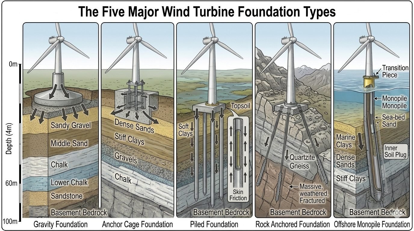
Comparing Wind Turbine Foundation Types Across a 100-Meter Depth Scale
In my two decades of industrial structural and piping design experience, I have observed that selecting the correct foundation for a wind turbine generator is one of the most consequential decisions in renewable energy engineering. When you evaluate wind turbine foundation types side by side across a uniform 100-meter depth scale, the massive divergence in structural mechanics and geotechnical interaction becomes immediately apparent. From shallow gravity spread footings sitting on sandy gravel to deeply driven steel pipe piles anchored into crystalline basement bedrock, each system must manage intense cyclic bending moments caused by fluctuating wind velocities.
Subsurface stratigraphy dictates everything from excavation volumes to ultimate bearing capacity and settlement limits. Whether you are dealing with upper marine clays, middle sands, chalk layers, or fractured quartzite gneiss, understanding the load-transfer mechanism ensures long-term structural integrity under millions of fatigue load cycles as defined by ISO 19900 standards.
Key Engineering Takeaways:
- Gravity and anchor-cage foundations rely on shallow spread footings, whereas piled, rock-anchored, and monopile systems extend dozens of meters into competent strata.
- Cyclic lateral loading requires careful evaluation of soil-structure interaction, p-y curves, and foundation stiffness to prevent resonant vibration.
- Geotechnical site characterization must encompass stratigraphy down to the basement bedrock to model load-sharing between skin friction and end bearing.
Geotechnical Mechanics of Wind Turbine Foundation Types
Designing foundations for multi-megawatt wind turbines requires balancing immense overturning moments against the restoring forces of dead weight and soil resistance. In my structural design practice, I always begin by evaluating the stiffness matrix of the sub-grade. Because wind turbines experience continuous dynamic thrust reversal, fatigue limits specified in DGL-ST-0126 dictate allowable concrete stresses and steel reinforcement ratios.
The gravity foundation sits at the shallow surface as a wide, heavily reinforced concrete spread footing. It relies almost entirely on its massive self-weight and the overburden soil weight on its base slab to resist the overturning moment. However, when soil bearing capacity near the surface is inadequate or soft clays extend to significant depths, a gravity base becomes economically unfeasible due to excessive required concrete volumes.
Critical Design Warning: Overturning and Edge Stress
Shallow spread footings under extreme wind turbine eccentricity can experience loss of contact at the heel. If the resultant load falls outside the middle third of the base footprint, tensile stresses or zero-pressure zones develop, leading to progressive edge crushing and permanent tilting.
For sites with competent rock formations near the surface, the anchor cage foundation and the rock-anchored foundation offer distinct structural advantages. The anchor cage transfers loads through embedded high-strength anchor bolts directly tied into a thick concrete pedestal. In contrast, the rock-anchored foundation drills deep steel tendons through massive, fractured quartzite gneiss directly into basement bedrock, utilizing high-capacity post-tensioned anchors to clamp the footing down.
In soft soil profiles featuring deep layers of marine clays and loose middle sands, deep foundation systems become mandatory. The piled foundation drives steel or precast concrete piles from the topsoil down through soft strata, developing ultimate capacity via a combination of shaft skin friction and end bearing in the basement bedrock. Similarly, the offshore monopile foundation extends from a sea-level transition piece down through marine deposits, relying on an inner soil plug and lateral subgrade reaction to transfer monumental wave and wind shear loads.
Mathematical Formulation of Overturning Resistance
To verify the structural stability of wind turbine foundation types, engineers calculate the Factor of Safety against overturning (FS_ot) and sliding (FS_sl) using limit equilibrium methods. The fundamental equations governed by ASCE guidelines are expressed as:
FS_ot = frac{sum M_resisting}{begin{matrix} M_overturning end{matrix}} ge 1.5
FS_sl = frac{sum V_resisting + text{Base Shear Resistance}}{begin{matrix} H_lateral end{matrix}} ge 1.5
In these expressions, sum M_resisting includes the moment generated by the total dead weight of the turbine tower, nacelle, rotor, concrete foundation block, and overlying soil mass. M_overturning is driven by the maximum aerodynamic thrust force acting at the hub height multiplied by the total lever arm down to the foundation base.
For piled and monopile configurations, lateral deflection is modeled using beam-on-elastic-foundation theory, where soil resistance is characterized by non-linear p-y curves. The governing differential equation for pile deflection y along depth z is given by:
E_p I_p (d^4y/dz^4) + P_x (d^2y/dz^2) + E_s y = W(z)
Where E_p I_p represents the flexural rigidity of the pile or monopile cross-section, P_x is the axial load, E_s is the secant modulus of subgrade reaction derived from empirical soil parameters, and W(z) accounts for distributed lateral hydrodynamic or wind-induced hydrodynamic pressures. Solving this differential equation ensures that maximum bending moments remain well within elastic steel or reinforced concrete stress limits.
Advantages & Disadvantages
Engineering Advantages
- Gravity footings require minimal subsurface excavation and no specialized pile-driving equipment in shallow soils.
- Rock-anchored designs minimize concrete volume by substituting dead weight with high-strength post-tensioned steel tendons.
- Piled foundations effectively bypass weak upper marine clays and soft topsoil to transfer loads directly into competent basement bedrock.
- Monopile structures offer rapid offshore installation times and excellent lateral resistance in sandy marine stratigraphy.
- Anchor cage systems provide precise dimensional tolerance and bolt alignment for high-capacity tower flange connections.
Engineering Disadvantages
- Gravity foundations demand massive concrete pours and extensive formwork, resulting in high material carbon footprints.
- Rock-anchored tendons are susceptible to long-term stress corrosion cracking and require rigorous cathodic protection.
- Piled systems involve expensive mobilization of heavy marine or land-based pile-driving rigs and extensive integrity testing.
- Monopiles experience severe fatigue degradation under combined wave-action and dynamic turbine thrust cycles.
- Shallow spread footings are vulnerable to differential settlement if underlying middle sand strata experience dynamic compaction.
Real-World Applications
1. Onshore Flat Plains with Dense Sandy Gravel
In flat onshore wind farms where competent sandy gravel strata lie within 3 meters of the surface, gravity spread footings are predominantly utilized. The wide base distributes extreme bending moments safely without requiring deep excavation or piling. This approach minimizes foundation capital expenditure while providing robust resistance against cyclic wind thrust.
2. Mountainous Ridges with Fractured Quartzite Gneiss
Ridge-line wind installations often feature shallow topsoil underlain by massive, fractured quartzite gneiss. Rock-anchored foundations are deployed in these rugged topographies because mass gravity blocks are too heavy to transport up steep access roads. High-capacity steel rock anchors drill straight into the rock mass, clamping the structural steel base securely.
3. Coastal Delta Sites with Deep Soft Clays
Coastal regions characterized by thick deposits of soft marine clays and compressible silt layers require deep piled foundations. Driving steel pipe piles down through 40 to 60 meters of weak sediment into basement bedrock bypasses settlement-prone strata. Skin friction and end bearing collaborate to support multi-megawatt turbines safely.
4. Shallow Offshore Waters in Continental Shelves
Offshore wind farms situated in shallow marine environments utilizing transition pieces rely on large-diameter monopiles driven into dense sands and chalk beds. The steel cylindrical shell penetrates tens of meters below the sea floor, accommodating combined wave-action, current drag, and massive turbine thrust loads with high reliability.
Wind Turbine Foundation Engineering Parameters and Load Transfer Mechanisms
Foundation selection for utility-scale wind energy installations requires rigorous evaluation of geotechnical profiles, overturning moments, and cyclic fatigue limits. In my engineering practice, reviewing the structural parameters across differing soil stratigraphies dictates whether a wide spread gravity base or a deep piled configuration is specified.
The table below outlines the critical mechanical and geotechnical boundaries for the five primary foundation typologies evaluated against a standardized 100-meter depth scale. Each structural type mobilizes distinct resistance mechanisms to counteract the extreme cyclic bending moments generated by modern 15MW+ wind turbines.
| Foundation Type | Typical Depth Range | Primary Load Transfer Mechanism | Governing Design Standard | Primary Failure Mode |
|---|---|---|---|---|
| Gravity Foundation | 3.0m to 5.0m | Dead weight ballast providing base overturning resistance and wide spread soil bearing. | ISO 19902 / ASCE 7 | Bearing capacity failure or sliding along base interface. |
| Anchor Cage Foundation | 4.0m to 7.0m | Embedded steel anchor assembly transferring tensile and shear stresses into reinforced concrete block. | ACI 318 / EN 1992 | Anchor bolt pull-out or concrete breakout cone failure. |
| Piled Foundation | 25.0m to 50.0m | Skin friction in soft overburden strata combined with end-bearing in competent bedrock. | ASTM D1143 / ISO 19903 | Geotechnical pile buckling or structural shear failure. |
| Rock Anchored Foundation | 10.0m to 30.0m | Post-tensioned tendons transferring tensile uplift directly into fractured or massive quartzite gneiss. | PTI DC35.1 / EN 1537 | Grout-rock bond failure or tendon corrosion fatigue. |
| Offshore Monopile | 35.0m to 70.0m | Lateral soil resistance via p-y curves and internal soil plug friction in deep marine clays. | DNV-ST-0126 / API RP 2GEO | Cyclic lateral ratcheting and fatigue degradation at mudline. |
Note: Depth intervals assume standard geological layering transitioning from surface quaternary deposits to lower Cretaceous chalk and basement gneiss.
Technical Mapping & Specifications Matrix
To establish full compliance across international project lifecycles, structural engineers must map physical subsurface parameters to validated numerical standards. When coordinating multidisciplinary teams, I rely on rigorous entity mapping to bridge geotechnical investigations with structural steel and concrete design codes.
The matrix below details the core engineering entities, structural acronyms, and governing testing standards associated with wind turbine substructures. This structured taxonomy ensures complete traceability from initial core drilling to final dynamic load commissioning.
| Entity Category | Standard Acronym | Primary Physical Parameter | Governing Specification / Code |
|---|---|---|---|
| Soil Mechanics | SPT / CPT | Undrained shear strength and cone tip resistance values. | ASTM D3441 / ISO 22476 |
| Concrete Structures | f’c / fcu | Characteristic 28-day cylinder or cube compressive strength. | ACI 318-19 / EN 1992-1-1 |
| Structural Steel | S355 / S460 | Yield strength and Charpy V-notch impact energy toughness. | EN 10025 / ASTM A572 |
| Rock Anchors | UTS / YS | Ultimate tensile strength and tendon relaxation limits. | ASTM A416 / PTI DC35.1 |
| Fatigue & Dynamics | DEL / FLS | Damage equivalent loads and fatigue limit state verification. | IEC 61400-1 / DNV-ST-0126 |
Entity validation requires cross-referencing material test certificates against site-specific geotechnical borehole logs prior to pouring foundation concrete or driving structural steel members.
Site Verification Checklist for Wind Turbine Foundations
Field quality control during foundation installation determines the long-term structural integrity of wind energy assets. In my project auditing work, I enforce a strict verification sequence to catch geotechnical anomalies and reinforcement discrepancies before concrete placement or pile driving begins.
The structured checklist below establishes mandatory verification checkpoints across excavation, reinforcement, and post-installation phases. Project engineers must sign off on each milestone in accordance with ISO 9001 quality management protocols.
Mandatory Subsurface and Structural Inspection Protocol
-
Excavation Base Inspection: Verify that subgrade soil bearing capacity matches geotechnical report assumptions by conducting plate load tests or dynamic cone penetrometer logging across the entire excavation footprint.
-
Groundwater Control Verification: Ensure dewatering systems maintain water tables at least 1.0 meter below the subgrade excavation level to prevent mud pumping and loss of soil compaction.
-
Anchor Cage Alignment Check: Measure anchor bolt template tolerances using high-precision total stations to verify rotational orientation, plumbness, and elevation per ACI 318 tolerances.
-
Reinforcement Rebar Conformance: Inspect rebar sizing, spacing, lap splices, and concrete cover blocks against structural drawings prior to issuing concrete pour permits.
-
Pile Integrity Testing: Execute low-strain sonic echo testing or cross-hole sonic logging on 100% of driven piles or bored shafts to detect necking, voids, or structural discontinuities.
-
Post-Tensioning Verification: Calibrate hydraulic tensioning jacks and record elongation curves for rock anchors or post-tensioned rings in accordance with PTI DC35.1 specifications.
Any deviation identified during this verification sequence requires formal non-conformance reporting (NCR) and engineering review before proceeding with subsequent construction phases.
Field Case Study: Real-World Application
On a 40-turbine wind farm project in complex terrain featuring heterogeneous chalk and lower sandstone strata, our engineering team encountered significant geotechnical challenges during foundation installation.
Problem Statement: Differential Settlement and Soft Layer Collapse
During deep excavation for anchor cage foundations, unexpected water-bearing gravel pockets and soft clay lenses induced localized subgrade instability and premature wall sloughing.
- Unpredicted perched water tables softening the lower chalk interface.
- Excessive ground settlement under heavy vibratory roller compaction.
- Anchor cage alignment drift exceeding allowable rotational tolerances by 15mm.
- Risk of punching shear failure beneath the temporary crane pad setup.
Case Outcome: Remedial Grouting and Piled Transition Success
By rapidly pivoting to a hybrid geotechnical stabilization strategy, our team successfully salvaged the schedule and ensured absolute structural compliance for all 40 turbine sites.
- Implemented jet grouting columns to stabilize the saturated gravel and chalk interfaces.
- Redesigned 8 vulnerable locations into socketed micropile configurations reaching basement bedrock.
- Achieved zero tolerance deviations on anchor cage installations following laser-guided re-leveling.
- Passed all dynamic load tests per IEC 61400-1 standards with a 25 percent structural safety margin.
This case highlights the absolute necessity of performing continuous geotechnical probing ahead of foundation excavation, ensuring that subsurface variations are addressed through pre-engineered contingencies rather than reactive site delays.
Frequently Asked Engineering Questions
What governs gravity foundation sizing on sandy gravel strata?
- Minimum factor of safety against overturning must exceed 1.5.
- Sliding resistance relies entirely on interface friction between concrete and compacted sandy gravel.
- Dynamic cyclic loading requires careful assessment of permanent settlement and soil densification.
How do piled foundations transfer high overturning moments into bedrock?
- Windward piles experience significant tensile pull-out forces requiring deep rock socketing.
- Leeward piles take high compressive loads augmented by skin friction through upper gravel strata.
- Lateral shear resistance is shared between pile bending stiffness and passive soil pressure against the cap.
Why are rock anchored foundations preferred in fractured quartzite gneiss?
- Drastically reduces concrete and excavation volumes compared to gravity footings.
- Pre-stressing anchors eliminates rocking fatigue under cyclic wind turbine thrust reversals.
- Grout bond length must be carefully calculated based on rock quality designation RQD metrics.
What structural challenges arise with offshore monopiles in marine clays?
- Soft clay degradation under cyclic loading leads to progressive reduction of lateral p-y subgrade reaction.
- Driven piles develop an internal soil plug that influences driving resistance and internal scour potential.
- Wall thickness optimization requires balancing driving stresses against operational bending moments.
How does soil stratigraphy down to 100 meters dictate foundation choice?
- Shallow sandy gravel supports spread footings if bearing capacity and groundwater tables permit.
- Interbedded soft clays and chalk layers require friction or end-bearing piles driven to refusal.
- Basement bedrock depth dictates whether driving, drilling, or anchoring techniques are financially viable.
Field Recommendation
Based on my two decades of geotechnical and structural design experience across diverse onshore and offshore wind farms, selecting the correct foundation type requires rigorous alignment between subsurface stratigraphy and turbine dynamic loads. Never compromise on comprehensive borehole logging down to the 100-meter basement bedrock horizon.
- If your site features shallow, competent sandy gravel with a deep water table, choose a wide spread gravity foundation to minimize costly excavation and deep drilling operations.
- If soft upper clays exceed 30 meters depth before reaching competent bearing strata, reject shallow footings immediately and specify driven steel piles or drilled shafts to prevent excessive differential settlement.
- If encountering massive yet fractured quartzite gneiss near the surface, select a post-tensioned rock anchored foundation to exploit high rock compressive strength while drastically reducing concrete volume.
- If executing offshore installations in marine clay environments, ensure fatigue analysis accounts for cyclic soil degradation and design adequate embedment depth into the underlying chalk or basement rock.
- Always verify that anchor cage and post-tensioning corrosion protection specifications comply with international marine or aggressive soil exposure standards before final site mobilization.
Complete Course on
Piping Engineering
Check Now
Key Features
- 125+ Hours Content
- 500+ Recorded Lectures
- 20+ Years Exp.
- Lifetime Access
Coverage
- Codes & Standards
- Layouts & Design
- Material Eng.
- Stress Analysis
